The post Considerations for Complex Industrial Cooling Water Monitoring and Treatment appeared first on ChemTreat, Inc..
]]>This article was originally published in PPCHEM® Journal; PPCHEM® 2021, 23(5), 198–205; https://journal.ppchem.com/
Abstract
Heat exchangers are, of course, a critical component of power and heavy industrial plants. Many of these are water cooled, with the source being a cooling tower (commonly known as an open cooling system) or sometimes once-through cooling. Often, “closed” systems are also present, which are cooled by primary heat exchangers, but whose chemistry is significantly different from that of open systems. Successful chemical treatment of the wide variety of cooling systems in plants requires analysis of many factors, including the potential for corrosion, scaling, and microbiological fouling, system metallurgy, operating temperatures, and others, all of which are examined in this article. Also discussed are several significant improvements to chemical treatment programs in recent years, improvements that maintain proper heat transfer and reliability of cooling systems.
Introduction to Complex Industrial Cooling Water Monitoring and Treatment
At steam generating power plants, the primary water-cooled heat exchanger is the steam surface condenser, unless, of course, the plant has an air-cooled condenser (ACC). Several other heat exchangers are also present, including the turbine lube oil cooler, bearing cooling water heat exchanger, and the hydrogen cooler. Many additional heat exchangers are utilized at large industrial plants such as refineries, petrochemical plants, etc. A wide range of designs is possible: from shell-and-tube to plate-and-frame to jacketed systems and others. Cooling systems may be open or closed. These complex arrangements usually require a variety of treatment methods. Furthermore, unlike in modern power plants, where materials selection has gravitated towards all-ferrous metallurgy throughout the condensate, feedwater/economizer, and boilers, several metals may be present in industrial systems. Copper alloys are quite common as the tube material in shell-and-tube heat exchangers.
Factors Affecting Cooling System Performance
Many factors can influence cooling system and heat exchanger performance and reliability, with a general representation outlined in Figure 1.
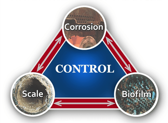
Figure 1. The corrosion-deposition-biofouling triangle.
As this diagram suggests, corrosion, scale formation, and biological fouling are not individually exclusive. A plant’s chemical treatment program needs to account for all three factors, and indeed the triangle could even be expanded to include environmental issues [1]. In the first portion of this article, we will focus on open systems, and primarily those supplied from cooling towers.
Open Cooling Systems
A classic example of concurrent issues can be seen in Figure 2, which shows a multi-pass tube-and-shell heat exchanger, whose cooling water at the time was treated with a traditional phosphate-based program.
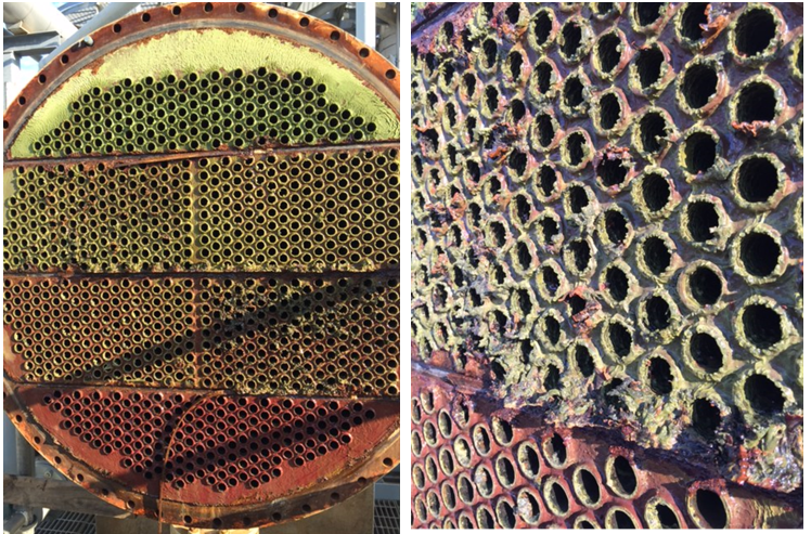
Figure 2. Multi-pass heat exchanger on a phosphate program just prior to a change in treatment chemistry.
At the inlet end of the heat exchanger (the tubes on the bottom of this unit), corrosion was problematic. At the warmer outlet side (on the top), deposition and scale formation was occurring. Thus, the program was not particularly effective at mitigating corrosion or deposition depending on location. We will return to this example later in the article.
From a microbiological perspective, cooling systems provide an ideal environment, warm and wet, for microbes to proliferate and form colonies. Bacteria can grow in heat exchangers and cooling tower fill, fungi on and in cooling tower wood, and algae on wetted cooling tower components exposed to sunlight. A major problem with microbes, particularly some bacteria, is that once they settle on surfaces, the organisms secrete a polysaccharide layer (slime) for protection. This film can severely inhibit heat transfer, and it can also collect silt from the water and grow thicker, further degrading heat exchange (see Figure 3). Biofilms restrict heat transfer more effectively than almost any other deposit. Furthermore, heavy fouling can drastically reduce fluid flow, sometimes to the point of complete blockage.
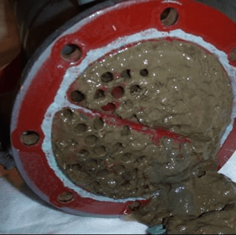
Figure 3. Heat exchanger tubes fouled with microbes and slime.
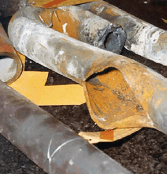
In another nod to Figure 1, the protective slime layer formed by initial bacterial deposits allows anaerobic and facultative bacteria underneath to flourish. These organisms can generate acids and other harmful compounds that directly attack metals. Microbial deposits also establish concentration cells, where the lack of oxygen underneath the deposit causes these locations to become anodic to other areas of exposed metal. Metal loss occurs at the anodes, with pitting as the result (see Figure 4).
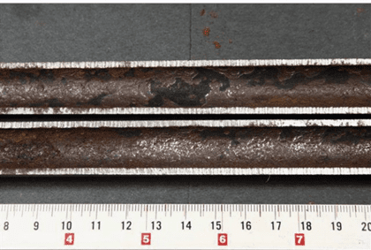
Figure 4. A large under-deposit corrosion pit (with deposit removed) in a stainless steel heat exchanger tube.
Of course, proper chemistry control to minimize fouling and scaling is a key method to help maintain heat exchanger reliability and performance, as we will explore later, but a benefit of the shell-and-tube design over others is the ability, in many cases, to remove slimy deposits and some hardness compounds by mechanical cleaning. Mechanical cleaning of other heat exchangers, for example plate-and-frame units (Figures 5a b), can be much more difficult, if not impossible.
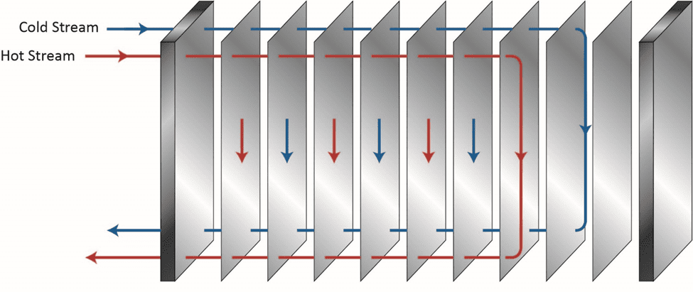
Figure 5a. Basic flow diagram of a single-pass plate-and-frame heat exchanger.
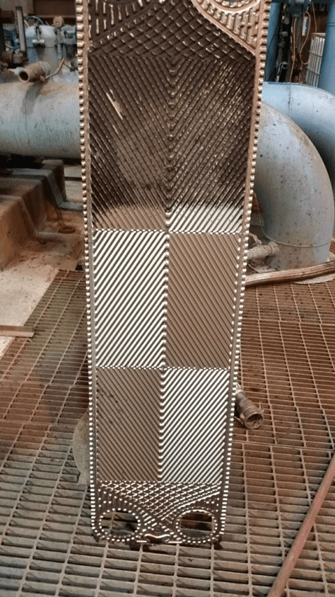
Figure 5b. An individual plate from a plate-and-frame heat exchanger. Lower part of the plate already cleaned by water jet washing, upper part uncleaned, exhibiting fouling that reduced heat transfer.
The narrow spacing between the plates offers a prime setup for fouling and deposition, and as Figure 5b illustrates, the plates are often designed with a corrugated or similar pattern to enhance fluid turbulence and heat transfer. Even so, fouling and deposition cannot be hindered completely.
Another very important aspect of corrosion/deposition issues in heat exchangers is the wall surface, also known as the skin, temperature. While the general increase in bulk cooling water temperature as the water passes through a heat exchanger can influence many reactions, additional or more pronounced reactions are possible at the metal surface, where temperatures may be significantly higher than in the bulk water. This is a factor to consider when evaluating heat exchanger design, metallurgy, and chemical treatment programs.
Don’t Forget the Cooling Towers
Cooling towers are another set of heat exchangers susceptible to corrosion, scaling, and especially fouling. Figure 6a shows cooling tower fill with heavy fouling. In Figure 6b, long algae threads hang from the fill to nearly the cooling tower basin.
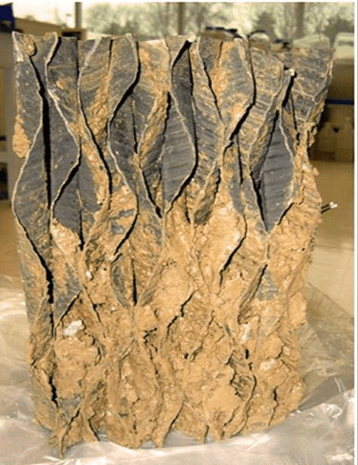
Figure 6a. Fouled cooling tower film fill.

Figure 6b. Severe algae growth in a cooling tower.
Control Techniques
Treatment methods for controlling the “big three” issues of the Figure 1 triangle have been addressed by the authors in a previous article for this journal [2]. To recap: During the middle of the last century, chromate (CrO42-) coupled with sulfuric acid feed was very popular for corrosion and scale control in many cooling systems. While chromate is considered an anodic inhibitor, with sufficient dosage, it will form a complete surface layer of iron chromate (pseudo-stainless steel), which can be quite protective. Acid feed to maintain a cooling water pH within a 6.5–7.0 range converts much of the bicarbonate ion (HCO3–) alkalinity to CO2, which escapes as a gas. Reduction of alkalinity greatly reduces the potential for calcium carbonate (CaCO3) scaling, which is typically the first mineral deposit that would otherwise precipitate without treatment. Chromate/acid chemistry is very straightforward and effective; however, environmental issues related to chromium discharge, particularly with respect to the toxicity of hexavalent chromium (Cr6+), led to abandonment of this method.
Treatment then evolved to phosphate-based chemistry for both scale and corrosion prevention. These programs typically function at a mildly alkaline pH range of approximately 8.0–8.5, which minimizes general corrosion. The chemistry also provides additional corrosion protection, as phosphate will react with ferrous ions (Fe2+) produced at anodic sites to form a reaction-limiting deposit, while calcium phosphate (Ca3(PO4)2) precipitates in the local alkaline environment at cathodic sites to inhibit electron transfer. However, even small upsets in phosphate programs can cause severe calcium phosphate fouling, and at one time, Ca3(PO4)2 deposition became almost as great a problem as calcium carbonate scaling had been before. Treatment methods evolved to more forgiving methodologies, with organic phosphate (also known as phosphonate) as the backbone in many cases, supplemented with polymer for calcium phosphate deposition control. Phosphonates attach to deposits as they are forming and disrupt crystal growth and lattice strength.
Even with these improvements, many problematic issues remain with phosphate/phosphonate treatment, including increasing concern about phosphorus discharge to the environment. These issues have led to advanced methodologies with the core functionality based on reactive polyhydroxy starch inhibitor (RPSI) chemistry as exemplified by, for example, ChemTreat’s FlexPro® technology. By virtue of many active sites on the molecules, these compounds attach to the base metal and form a protective layer. Common RPSI formulations also include advanced polymers that inhibit scale formation by crystal modification and ion sequestration. Figure 7 shows the same heat exchanger from Figure 2 following cleaning and changeover to FlexPro® treatment.
Figure 7. The heat exchanger from Figure 2 on FlexPro® chemistry. Tubes are essentially free of corrosion and deposition.
Most modern cooling tower chemical treatment programs operate in a mildly basic pH range of 8.0–8.5. Chlorine gas was the workhorse for microbiological treatment for many years, although liquid bleach (NaOCl) feed supplanted gaseous chlorine at many plants for safety reasons. When chlorine is added to water, the following reaction (Eq. (1)) occurs:
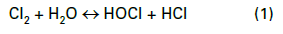
Hypochlorous acid (HOCl) is the killing agent, and it functions by penetrating cell walls and oxidizing internal cell components. The efficacy and killing power of this compound are greatly affected by pH because of the equilibrium nature of HOCl in water, as shown in Eq. (2).

OCl– is a much weaker biocide than HOCl, probably because the charge on the OCl– ion does not allow it to effectively penetrate cell walls. The dissociation of hypochlorous acid dramatically increases as the pH rises above 7.5. Because many cooling tower scale/corrosion treatment programs operate at an alkaline pH, chlorine chemistry may not be the best choice for some applications. Chlorine efficiency is further influenced by ammonia and organics in the water, which react irreversibly with the chemical and increase chlorine demand.
A popular solution to this difficulty has been bromine chemistry, where a chlorine oxidizer (bleach is the common choice) and sodium bromide (NaBr) are blended in a makeup water stream and injected into the cooling water. This chemistry produces hypobromous acid (HOBr), which has similar killing powers to HOCl but functions more effectively at an alkaline pH. Figure 8 compares the dissociation of HOCl and HOBr as a function of pH.
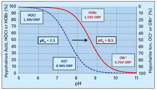
Figure 8. Dissociation of HOCl and HOBr vs. pH.
Many facilities such as refineries, chemical plants, steel and paper mills, food and beverage plants, etc., often have cooling systems with waters containing elevated organics, nitrogen species, or other impurities that severely inhibit the performance of conventional oxidizers. Accordingly, ChemTreat researchers have improved upon and developed alternative oxidizing biocides that may perform much more effectively in difficult cooling waters. One is monochloramine (NH2Cl) with precise generation for each application. This compound is a weaker oxidizer than chlorine or bromine, but research and operating experience show the chemical to be more effective than chlorine or bromine at penetrating the protective bacterial slime layer that consumes stronger oxidants.
Another option is a specialty solution of chlorine dioxide (ClO2). This compound is a selective oxidizer, but even though it is chlorine-based, it does not react with ammonia and reacts less vigorously with some organics than chlorine. Furthermore, the compound is not influenced by pH. On-site chlorine dioxide generation is required, as large quantities of chlorine dioxide cannot be safely stored in containers or tanks. However, most modern production methods include more safeguards and safety checks than past technologies.
For those plant personnel who still wish to use bleach (sodium hypochlorite), but whose cooling systems face at least some of the challenges mentioned above, the use of halogen stabilizers may be a good choice. These products typically contain a combination of halogen stabilizer and bio-penetrant. The former, as its name implies, stabilizes the chlorine in solution and provides a controlled release. The bio-penetrant aids biocide efficacy by destabilizing protective slime layers to allow the oxidizer better access to the underlying organisms.
At some plants, oxidizer feed is limited to two hours per day, which gives microbes time to settle and form colonies during off times. Accordingly, a supplemental feed of nonoxidizing biocide on perhaps a once-per-week basis can be quite effective in controlling biological growth. Nonoxidizers in conjunction with bio-penetrants reduce overall chlorine usage and do not produce halogenated organic byproducts. Table 1 below lists properties of some of the most common nonoxidizers.
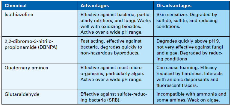
Table 1. Nonoxidizing biocides.
Careful evaluation of the microbial species in the cooling water is necessary to determine the most effective biocides. Antimicrobial compounds should not be used or even tested without approval from the appropriate regulating agency. They must be incorporated into the plant’s discharge permit. Also, as with all chemicals, safety is an absolutely critical issue with biocides. Safety Data Sheet (SDS) guidelines should be followed to the letter when handling these products.
Closed Cooling Water (CCW) Treatment
Many plants have numerous heat exchangers that are usually embedded in a closed cooling water system, which rejects heat to the primary open recirculation cooling system (see Figure 9).
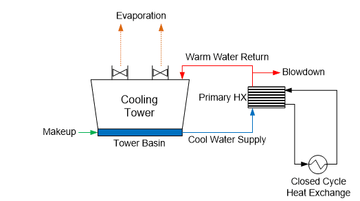
Figure 9. General schematic of a primary open-recirculating and secondary closed cooling system arrangement.
The term “closed” cooling water system is somewhat of a misnomer, as virtually all systems have leaks or small losses somewhere that require makeup. (If serious corrosion has occurred, these losses may be significant.) Systems are often designed with a head tank for water makeup and handling changes in demand. This arrangement can allow some oxygen to enter the cooling water, which, of course, influences the corrosion potential.
While it may be possible to utilize water with varying qualities in CCW systems, a common choice, and our main focus here, is specially-treated condensate or demineralized water. Choosing condensate over less pure water minimizes the possibility of difficulties from scale-forming hardness compounds or corrosive agents such as chloride and sulfate.
A typical piping material for CCW systems is carbon steel, with stainless steel or perhaps copper alloys being a common choice for heat exchanger tubes or plates in plate-and-frame exchangers. Other metals may include aluminum or those metals contained in the solder of fittings within heat exchanger cooling coils. When planning a treatment program, it is important to know the entire system metallurgy.
Corrosion inhibitors slow reactions at either the anode, the cathode, or sometimes both sites of electrochemical cells. A very common treatment method, based on cost and ability to protect carbon steel, is nitrite applied via injection of sodium nitrite (NaNO2) to the cooling circuit. When carbon steel is first placed into service, the metal surface develops an oxide layer. While formation of this oxide coating is a corrosion mechanism, the layer serves as a protective film for the base metal underneath. However, the natural oxide layer can be damaged by mechanical influences or penetrated by corrosive agents. Nitrite forms a passivating iron oxide film at anodes that can eventually cover the entire steel surface. A representative reaction of this chemistry is outlined in Eq. (3).

An important aspect to be noted from this equation is that the nitrite reaction produces ammonia, which can induce corrosion of copper alloys, particularly if an oxidizing element or compound such as oxygen is also present in the water. The pH of these solutions is typically adjusted to a range of 8.5–11 with an alkaline compound such as sodium hydroxide or the buffering agent sodium tetraborate, commonly known as borax.
A key concept with regard to anodic inhibitors such as nitrite is that the chemical concentration should not be allowed to fall below a minimum value. If the level drops too low, anodes will develop in what is otherwise a large cathodic environment, establishing localized sites for very intense corrosion. Through-wall pitting may be the result. A common range for nitrite concentration is 500–1,500 mg∙L-1. The authors have worked with closed cooling systems in which this range could not be maintained because of significant leaks. Treatment was suspended to protect the remainder of the piping from localized corrosion. The proper response to such issues is repairing and replacing corroded piping to return the system to “closed” status. Plant management may not always agree with this philosophy because of the cost and complexity of the task. However, large leakage requires large makeup. Excessive feed of oxygen-saturated makeup propagates corrosion.
One disadvantage of nitrite treatment is that the chemical serves as a nutrient for certain bacteria, such as Nitrobactera Agillis, which converts nitrite into nitrate (NO3–), which, in turn, can generate significant slime. Author Brad Buecker once observed a nitrite-treated closed cooling water system at a large automobile assembly plant, in which microbial slime restricted flow in the small-bore cooling coils of automated welding devices. Overheating became a problem. Also, some microorganisms, via their metabolic processes, produce acids and other harmful byproducts that can directly attack metals via the mechanism known as microbiologically-induced corrosion (MIC).
Another corrosion inhibitor option, albeit a more expensive one, is molybdate (MoO42-), which is generated by the addition of sodium molybdate (Na2MoO4) to the cooling water. Like chromate, molybdate binds with iron to form a surface layer of ferrous molybdate (FeMoO4). This compound provides good protection, particularly against the harmful anions chloride and sulfate. A common dosage range is 200–1000 mg∙L-1, with a typical recommended pH range of 9.0–11.0. Nitrite and chromate can be blended to provide a synergistic effect, where the nitrite enhances tighter molybdate bonding. Often in these cases, the control range for each chemical is slightly lower than if utilized individually.
Other protection methods are available, including protection by silicates, and the use of a reducing agent such as hydrazine to maintain the passive Fe3O4 (magnetite) layer on carbon steel and cuprous oxide (Cu2O) on copper alloys. However, for copper alloys, azole chemistry is often the best choice. A common member of the azole group is tolyltriazole (TTA), whose structure is shown in Figure 10.
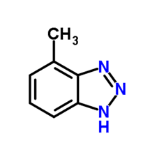
Figure 10. Basic structure of TTA.
When utilized in basic solutions, which is common for nitrite and molybdate, the molecule deprotonates (loses the hydrogen ion), and nitrogen bonds to the copper surface. The organic rings of the compound form a plate-like film to protect the base metal.
CCW Microbiological Control
In a closed system with no organic loading, the conditions are theoretically unfavorable for microbiological fouling. Yet, as has already been noted, fouling can be problematic in some systems, and particularly those that use some form of organic chemicals, e.g., azoles or dispersants, which can break down and provide food for microbes. Add a nutrient such as nitrite, or its reaction product, nitrate, and significant problems may arise. If the system utilizes water other than condensate, other microbes such as sulfate-reducing bacteria may proliferate.
Therefore, microbiological treatment may be necessary, but unlike open cooling systems, oxidizing biocides are typically not utilized in closed systems. Oxidizers can react with some corrosion inhibitors such as nitrite or introduce corrosive species, e.g., chloride, to the water. Nonoxidizing biocides are the preferred choice, some of which have already been discussed above for open systems.
Conclusion
Large industrial plants typically have numerous heat exchangers, usually of many different sizes, designs, and metallurgies. A “one-size-fits-all” chemistry program will not work for these complex arrangements, and a thorough analysis of each system is appropriate for optimizing chemical treatment programs. Included in the heat exchanger list are cooling towers, which often sit in far corners of the plant or on top of buildings, where minimal attention is often paid until an upset occurs.
Of course, each system is different and has unique treatment needs, and due diligence is necessary for determining the feasibility for utilizing these methods. Always consult your equipment manuals and guides and contact a water treatment professional before making changes to your systems and treatment processes.
References
1. Buecker, B., “Environmental Considerations in the Advancement of Cooling Treatment Technology”, Water Technology 2021, 44(3). Available from https://www.watertechonline.com.
2. Post, R. M., Kalakodimi, R. P., and Buecker, B., “An Evolution in Cooling Water Treatment”, PowerPlant Chemistry Journal 2018, 20(6), 346.
The Authors
Brad Buecker (B.S., Chemistry, Iowa State University, Ames, IA, USA) is a Senior Technical Publicist with ChemTreat. He has many years of experience in or affiliated with the power industry, much of it in steam generation chemistry, water treatment, air quality control, and results engineering positions with City Water, Light & Power (Springfield, IL, USA) and the Kansas City Power & Light Company’s (now Evergy) La Cygne, KS, USA, generating station. He also spent two years at a chemical manufacturing plant and an additional 11 years at two engineering firms. He is a member of the ACS, AIChE, ASME, AIST, AMPP (NACE), the Electric Utility Chemistry Workshop planning committee, and the Power-Gen International planning committee. Mr. Buecker has authored many articles and three books on power plant topics.
Prasad Kalakodimi (M.S., Physical Chemistry, Andhra University, Andhra Pradesh, India, Ph.D., Electrochemistry, Indian Institute of Science, Bangalore, India) received his Ph.D. in 2003. Dr. Kalakodimi is currently the Director of Applied Technology for ChemTreat, Inc., in Glen Allen, VA. Prior to joining ChemTreat, Dr. Kalakodimi served as the engineering technical leader at the GE India Technology Centre in Bangalore and as product manager for chemicals and monitoring solutions for GE Water. He has over 20 patent filings, 20 international publications, and various conference presentations.
Contact us to learn more and request a consultation.
The post Considerations for Complex Industrial Cooling Water Monitoring and Treatment appeared first on ChemTreat, Inc..
]]>The post Monitoring Industrial Plant Discharge Metals and TOC appeared first on ChemTreat, Inc..
]]>This article was originally published in PPCHEM® Journal; PPCHEM® 2021, 23(4), 152–157; https://journal.ppchem.com/
Abstract
Industrial facilities such as refineries, petrochemical plants, steel mills, metal finishing facilities, pulp and paper mills, pharmaceutical plants, etc. require substantial wastewater treatment, as some processes at these facilities can release many complex carbon compounds or other toxic constituents, including metals, to waste streams.
While various techniques are available for measuring trace level metals in process water, to date they have been rather unavailable to many industrial locations because of capital cost requirements or the need for specially trained technicians. Two well-known techniques are inductively-coupled plasma and atomic absorption spectroscopy, which need specially trained operators and require complex sample preparation and expensive instrumentation.
This article discusses another existing technology, colorimetry, which has been modified for on-line monitoring. The method is suitable for many facilities and can be operated by a wide range of plant personnel. In many cases, the readings can be enhanced with TOC analyses to provide additional protection for industrial water/steam systems.
Introduction to Monitoring Industrial Plant Discharge Metals and TOC
When author Brad Buecker began a lengthy career in the coal-fired power industry four decades ago, common discharge regulations for US power plants focused on four impurities or parameters: total suspended solids (TSS), pH, oil and grease (O&G), and residual oxidizing biocide concentration. These days, it is well recognized that many other wastewater impurities can cause problems for power producers. Of course, facilities such as refineries and petrochemical plants require substantial wastewater treatment, as refining and organic chemical synthesis can release many complex carbon compounds and toxic constituents to waste streams. Many other heavy industries such as steel mills, metal finishing facilities, pulp and paper mills, and pharmaceutical plants also deal with challenging wastewater treatment issues.
Along with these applications, discharges from other seemingly benign processes (e.g., cooling tower blowdown and storm water runoff) are facing increased regulation because of their potential negative effects on the natural environment. A well-known example is tighter regulation of phosphorus in cooling tower discharge, which was previously reported in this journal [1]. Ammonia is another impurity of concern; like phosphorus, it is a prime nutrient for the large algae blooms that have plagued many surface water bodies. New technologies that minimize or eliminate inorganic and organic phosphates for cooling tower water treatment have become very popular.
However, concern continues to grow over discharges containing transition and heavy metals, as well as metalloids. These constituents include zinc, copper, chromium, selenium, arsenic, and others. The ability to monitor trace concentrations of metals is important for plant operators and technical staff when evaluating the efficacy of treatment programs and ensuring compliance with discharge guidelines.
Metals of Concern and a Review of Some Treatment Techniques
While trace concentrations of some heavy metals are important for certain biological functions, others pose a significant danger to the environment and sometimes even to internal plant processes. Antimony, selenium, and arsenic are highly toxic even at very low levels. Chromium, arsenic, cadmium, mercury, and lead have a strong affinity for sulfur, and can bond to enzymes in the human body, inhibiting metabolic reactions. Arsenic, hexavalent chromium, manganese, and cobalt are carcinogens. Cadmium causes a degenerative bone disease. Mercury, lead, and manganese can damage the central nervous system. From an industrial perspective, manganese, aluminum, and iron can cause deposition and corrosion problems in plant process and cooling water systems. This list is not exhaustive, but it offers an indication of how serious the negative impacts of many metals can be [2-4].
Of course, much R&D has gone into treatment technologies for metals removal from process and wastewater streams. We will discuss several techniques before moving to the monitoring portion of this article. Perhaps somewhat surprisingly, many modern treatment methods do not rely on exotic equipment but have resulted from chemistry improvements within traditional processes. Consider the CoMag® ballasted clarification process [5]. Ballasted clarification has become popular, as these units operate with high rise rates, which, in turn, allow for clarifier design with much smaller footprints than conventional equipment. The original material for many ballasted clarifiers was micro-sand, which works well for providing a dense material to capture floc and improve settling. However, this precipitation process utilizes magnetite (Fe3O4) ballast. As with micro-sand, magnetite offers a dense substrate for settling enhancement, but with a significant advantage in that several heavy metals will co-precipitate with the iron and depart the system within the clarifier sludge. These trace metals or metalloids include copper, aluminum, and arsenic.
Another chemistry advancement relies on the aforementioned affinity of sulfur for certain metals. A leading example is mercury, which binds quite strongly with sulfur. Water treatment polymers with active sulfur sites have been developed for blending with other flocculating agents in standard clarifiers. These polymers can be quite effective for mercury removal, but sometimes the reaction is so fast that it generates very fine flocs. Care may be necessary to prevent the fine flocs from escaping with the clarifier overflow.
Another problematic impurity for several industries is selenium. Selenium is a naturally occurring element that, in power plant coal combustion, is typically released in two species, selenite (SeO3) and selenate (SeO4). These oxides are captured in ash sluicing or wet flue gas desulfurization (WFGD) streams. For years, the best available technology (BAT) for selenium removal, as determined by the United States Environmental Protection Agency, has been biological treatment per adsorption of the oxidized selenium compounds on an organic substrate, and subsequent digestion of the selenium oxides by microorganisms that convert the compounds to elemental selenium retained by the microbes. These systems are very large, expensive, and require periodic removal of spent organisms and replenishment of the microbiological substrates.
ChemTreat now offers SeQuester , which is a physical-chemical alternative to biological selenium removal. The process utilizes co-precipitation chemistry and pH adjustment to capture selenium in conventional wastewater treatment equipment such as clarifiers, holding tanks, and filter presses. The configuration can be designed to treat not only direct discharge from wet scrubbers, but also stored ash pond water, collected landfill leachate, and mine tailing discharges, all at potentially much lower cost than the current BAT methods. Furthermore, pilot test results indicate the technology may lower the concentrations of other trace metals, including arsenic, cadmium, chromium, lead, mercury, and silver [6].
Many coal plants, both operating and shuttered, are also struggling with environmental edicts to close ash ponds. Several well-publicized accidents have released large quantities of ash and water into the environment. Since pond remediation does not allow for the water to be directly drained to some other receiving body of water such as a river or lake, rigorous treatment may be necessary before ponds can be drained and closed.
A critical aspect to successful removal of impurities from wastewater streams is accurate monitoring of the contaminants, which brings us to the second section of this article.
Detection and Monitoring Methods for Metal Concentrations
We will now examine an existing and somewhat familiar technique for metals monitoring. The colorimetric method, with an option for digestion to determine both dissolved and total concentrations, has been adapted for on-line trace metal analysis.
Various criteria exist for categorizing metals. Generally, heavy metals are those that have a density greater than 5g ⋅ cm–3. This is the criterion selected for this discussion, even though other metals or metalloids such as aluminum and selenium may be of concern in various processes despite not formally fitting into this category [7]. Often, the transition metals are lumped in with heavier metals when it comes to certain properties.
A variety of technologies are currently available for monitoring trace metal concentrations. However, many methods only offer snapshot analyses of a sample obtained from the process stream of concern. Two well-known techniques are inductively-coupled plasma (ICP) and atomic absorption spectroscopy (AAS), which need specially trained operators and require complex sample preparation and expensive instrumentation.
Such methods may be acceptable when the water sample is not expected to change over short periods of time, e.g., 24 hours. However, in many process streams, upsets or deviations may frequently occur because of changes in some aspect of the overall process. In any of these instances, some type of on-line or continuous monitoring is needed for accurate evaluation of process conditions.
Before moving forward with this discussion, it is important to set forth some qualifications. Colorimetry requires a relatively clean sample, which may preclude the use of this technique in some industrial settings. In general, maximum particle size should be less than 100μm, at a concentration of less than 0.1g ⋅ L–1 and a turbidity (measured as nephelometric turbidity unit, NTU) of less than 50NTU. Total organic carbon (TOC) should be less than 25mg ⋅ L–1. These are meant to be guidelines only and not a guarantee of performance. Sample dilution, either internal to the analyzer or external, may be an option, including when color is present. Filtering is also possible for samples with suspended solids, but consideration should be given to whether the particles being removed contain any of the substances being measured. This being stated, the analytical method will now be described.
Metal Analysis Using Colorimetry
Many power plant and industrial chemists have utilized colorimetric techniques for years to track water/steam chemistry. Common parameters include phosphate, silica, and ammonia, with the technology having long ago advanced beyond grab sample measurements to continuous on-line analyses. In fact, applications for continuous phosphate monitoring continue to evolve. One example of this evolution is the increasing selection of reclaimed municipal wastewater as makeup supply for industrial plants. Accurate analyses of inlet phosphate concentrations are important for controlling cooling water treatment programs and other processes.
Grab sample colorimetric analysis for metals has also been a viable method for decades, but adapting colorimetry for on-line monitoring requires additional consideration. This can be accomplished using software-controlled valves that introduce the required reagents at the appropriate time.
The metals that can currently be analyzed with colorimetry are chromium, manganese, iron, nickel, copper, and zinc. While not considered as heavy metals, aluminum and boron, which have been shown to be detrimental to health and the environment at certain levels, can also be measured using this technique.
For those metals that exist as suspended particles, digestion is required to convert them to a dissolved state. Generally, this is accomplished via acid addition and heating to 120°C for a minimum of 10min. This step is performed in a separate digestion vessel per Figure 1. The sample is then cooled, transferred to the analysis vessel, and subjected to an initial absorbance reading taken before reagent addition. The proper analytical wavelength will conform to the specific metal and reagent combination responsible for the color development. The final absorbance is then measured after reaction of the reagent with the metal, with final calculation per Beer’s Law.
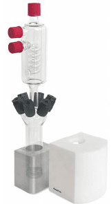
Figure 1: Digestion unit.
This method is summarized in Figure 2, and the correct chemical reagents vary depending on the metal to be analyzed. For example, adding ethylene-diamine-tetraacetic acid (EDTA) and a reducing reagent minimizes interferences when analyzing zinc or manganese. Some interference may still occur if the sample has large amounts of color, turbidity, and significant concentrations (mg⋅L–1 levels) of certain other metals.
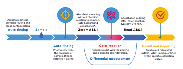
Figure 2: The colorimetric cycle. *If additional buffer is added, ABS1 is only read after addition of this buffer
It should be noted that although colorimetry has evolved into an on-line method, the analyses themselves are batch reactions. Depending on the metal and whether or not a digestion is required, analysis times can range from 10 to 30 minutes. While the use of an integrated sequencer can permit the analysis of up to 8 individual streams, the number of discreet readings per stream is reduced accordingly (e.g. with a 10-minute cycle time and 6 streams, only 1 reading per stream is reported per hour). A typical instrument with software-controlled valves, digestion vessel and colorimeter is illustrated in Figure 3.
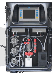
Figure 3: Hach EZ Process Analyzer.
TOC Monitoring
Another on-line monitoring parameter receiving increased and deserving attention is total organic carbon. As Figure 4 suggests, TOC data from numerous plant processes can be valuable.
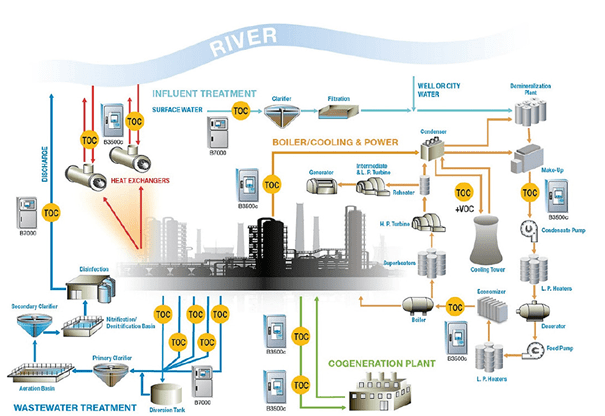
Figure 4: Potential TOC sampling sites at an industrial facility (illustration courtesy of Hach).
Naturally, at plants such as refineries and petrochemical facilities, continuous TOC monitoring of condensate return and other process water streams can alert personnel to leaking heat exchangers and other equipment. For example, one of the authors relatively recently visited a liquefied natural gas (LNG) import facility that was being converted into an export facility. A major part of the process is removing hydrocarbons larger than methane from the incoming natural gas before liquefaction. The condensate return lines to the co-generation plant have TOC analyzers to detect organic contamination that might enter from this and other processes.
Consider some of the other sample points in this diagram. TOC could be a front-line indicator of potentially harmful organic compounds leaving the plant in a wastewater stream. If the plant has a non-fresh water source for plant makeup, such as reclaimed municipal wastewater effluent, TOC could again be a front-line indicator of upset conditions at the municipal wastewater plant. It is not unknown for plants that handle combined wastewater and storm runoff to be overwhelmed during heavy rains and need to bypass some wastewater that has received only primary treatment. Organic carbon levels can increase dramatically in these conditions. An increase in TOC to cooling tower makeup can upset cooling water chemistry, cause difficulties in high-purity makeup treatment systems, and, most importantly, influence microbial growth in heat exchangers, cooling tower fill, and other locations.
Conclusion
While various techniques are available for measuring trace level metals in process water, to date they have been rather unavailable to many industrial locations because of capital cost requirements or the need for specially trained technicians. This discussion outlined an existing technology that has been modified for on-line monitoring. This method is suitable for many facilities and can be operated by a wide range of plant personnel. Additional R&D continues exploring instrumentation for analyzing other metals of concern in wastewater processes. In many cases, these readings can be enhanced with TOC analyses to provide additional protection for industrial water/steam systems.
Of course, all systems are different, and, as with all other technologies, due diligence is necessary to determine the feasibility of utilizing such methods. Always consult your equipment manuals and guides.
References
[1] Post, R. M., Kalakodimi, R. P., Buecker, B., “An Evolution in Cooling Water Treatment”, PowerPlant Chemistry 2018, 20(6), 346.
[2] Rusyniak, D. E., Arroyo, A., Acciani, J., Froberg, B., Kao, L., and Furbee, B., “Heavy Metal Poisoning: Management of Intoxication and Antidotes”, Molecular, Clinical and Environmental Toxicology Volume 2: Clinical Toxicology (Ed.: A. Luch), 2010. Birkhäuser Verlag, Basel, Switzerland, 365.
[3] Giacoppo, S., Galuppo, M., Calabrò, R. S., D’Aleo, G., Marra, A., Sessa, E., Bua, D. G., Potortì, A. G., Dugo, G., Bramanti, P., Mazzon, E., “Heavy Metals and Neurodegenerative Diseases: An Observational Study”, Biological Trace Element Research 2014, 161(2), 151.
[4] Duffus, J. H., “Heavy Metals – A Meaningless Term?”, Pure and Applied Chemistry 2002, 74(5), 793.
[5] The CoMag System for Enhanced Primary and Tertiary Treatment, 2017. Evoqua Water Technologies LLC, Waukesha, WI, USA. Available from https://www.evoqua.com.
[6] Djukanovic, V., Buecker, B., Karlovich, D., “Coal-Fired O&M: A Novel Non-Biological Process for Selenium Removal”, Power Engineering International 2020. Available from https://www.powerengineeringint.com.
[7] Baird, C., Cann, M., Environmental Chemistry, 2012. W.H. Freeman and Company, New York, NY, USA, 5th Edition.
Authors
Brad Buecker (B.S., Chemistry, Iowa State University, Ames, IA, USA) is a senior technical publicist with ChemTreat. He has many years of experience in or affiliated with the power industry, much of it in steam generation chemistry, water treatment, air quality control, and results engineering positions with City Water, Light & Power (Springfield, IL, USA) and the Kansas City Power & Light Company’s (now Evergy) La Cygne, KS, USA, generating station. He also spent two years at a chemical manufacturing plant and an additional 11 years at two engineering firms. He is a member of the ACS, AIChE, ASME, AIST, AMPP (NACE), the Electric Utility Chemistry Workshop planning committee, and the Power-Gen International planning committee. Mr. Buecker has authored many articles and three books on power plant topics.
Ken Kuruc (B.S., Chemistry, John Carroll University, Cleveland, OH, USA) has been active in the power industry for over 25 years. In his current role, Ken provides technical support on all aspects of water quality monitoring for fossil power generation sites across the USA. He has co-authored articles which have appeared in various power industry publications and has presented at numerous utility and water chemistry conferences, including the International Water Conference, where he was awarded the 2019 Paul Cohen Award.
Contact us to learn more and request a consultation.
The post Monitoring Industrial Plant Discharge Metals and TOC appeared first on ChemTreat, Inc..
]]>The post Modern Techniques for Corrosion/Fouling Protection in Mid-Sized Cooling Towers appeared first on ChemTreat, Inc..
]]>Much has been written about protection against corrosion, deposition, and microbiological fouling in large power and industrial cooling towers and cooling water systems. However, the hundreds of thousands of moderately sized cooling water systems that supply other industrial and commercial facilities are sometimes overlooked. This article examines several key aspects for optimizing cooling system performance and reliability. Readers can find additional information by investigating the Cooling Technology Institute (www.cti.org), whose annual conference, committee meetings, and library are excellent resources.
Read the rest of the article online.
The post Modern Techniques for Corrosion/Fouling Protection in Mid-Sized Cooling Towers appeared first on ChemTreat, Inc..
]]>The post Keys to Reliable Makeup Water Treatment for Boilers appeared first on ChemTreat, Inc..
]]>This article originally appeared in The Analyst, an AWT publication.
High-purity water is typically a must for power-producing steam generators, as the high-temperature/pressure conditions require control of impurities to low part-per-billion (ppb) concentrations to prevent serious corrosion and fouling. For the thousands upon thousands of low-pressure boilers at industrial plants around the country, however, water-purity requirements are usually not as stringent. Yet, incidents where poor design or failures in the makeup water treatment system have induced severe scaling and corrosion have been recorded for decades and continue to occur. These can lead to lost production and costly equipment repair or replacement. This article provides insight into the importance of makeup water treatment for low-pressure boilers and outlines modern technologies for producing good-quality makeup water at reasonable cost.
Low-Pressure Steam Generators
Low-pressure steam (pressures below 900 pounds per square inch gauge [psig] in general, and often between 50 and 600 psig) is used at many industrial plants around the country. For example, steam typically serves numerous processes at refineries, including as an integral heat source in atmospheric distillation, and in cracking and reforming processes. Steam feeds turbines for blast furnace air production at integrated steel mills; digesters and concentrators at paper mills; evaporators, crystallizers, and reaction vessels at chemical plants; and building heat systems everywhere. The list goes on and on.
The stimulus for this article comes from direct experience by the authors and too-frequent reports from our colleagues, who, upon entering plants for the first time find steam generators with serious scaling, corrosion, or steam purity issues that can be directly traced back to either poor design or inadequate attention to the makeup water system (and often condensate return chemistry). This frequently seems to occur as the result of plant management, operators, or technical staff focusing on process chemistry and engineering, with steam generation (and cooling water systems) appearing as rather nebulous entities that require less attention.
Most of the boilers in large industrial plants are the watertube style, frequently of the package type, although large boilers may be field-erected. Steaming rates (pounds per hour [lb/h]) are usually in the five to six-figure range. Commonly, these boilers include superheaters to raise the steam temperature above the saturation point and ensure the steam has the proper energy and/or remains dry until the point of use. For boilers that supply turbines, superheating is required to prevent excessive condensation in the turbine that could damage blades.
Makeup Treatment Issues
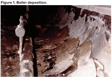
Probably from the time humans first began to heat water for personal needs, our species has observed deposition in heated vessels. These issues became much more acute following the invention and expanded use of the steam engine during the Industrial Revolution of the 18th and 19th centuries. The primary culprit was (and still often is) calcium carbonate deposition.

This equation outlines the reaction of calcium ions (Ca2+) and bicarbonate alkalinity (HCO3–) that can occur in hot water systems and boilers. A critical point to note is that CaCO3 is an inversely soluble salt, whose deposition potential increases with increasing temperature. As Figure 1 clearly illustrates, it is not a mechanism that has been relegated to the past.
As steam generators increased in pressure and power in the last century, methods to minimize and control CaCO3 scaling became necessary. A common solution from the 1930s onward has been makeup water sodium zeolite softening, a technology that became practical with the development of synthetic ion exchange resins (Figure 2).
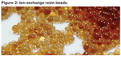
Each of these beads contains billions of active sites, which, for sodium softening, are typically sulfonic acid groups with sodium attached (SO3–Na+). Figure 3 illustrates a basic configuration of a softening vessel.
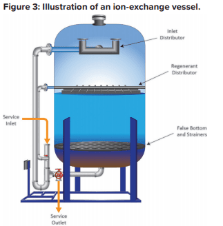
As makeup water passes through the vessel, calcium (Ca2+) and magnesium (Mg2+) exchange for sodium. The strongest affinity is for calcium followed by magnesium, so as a service run progresses, the resin develops stratified layers.
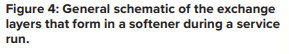
The softened stream, with hardness removed, still contains the other dissolved ions, including alkalinity, chloride (Cl–), sulfate (SO42-), and silica (SiO2). When the bed reaches exhaustion, it is regenerated with a brine solution that drives the hardness ions off into a waste stream, which is discarded.
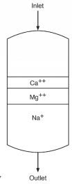
At this point, several features of sodium softening require some extra discussion. Many low-pressure steam-generating systems have been designed with sodium softening as the core boiler makeup treatment method, with no further treatment. And indeed, this may be sufficient for numerous steam generators. Table A outlines some general guidelines, extracted from a well-known American Society of Mechanical Engineers (ASME) source, regarding impurity limits in low- to medium-pressure watertube industrial boilers.
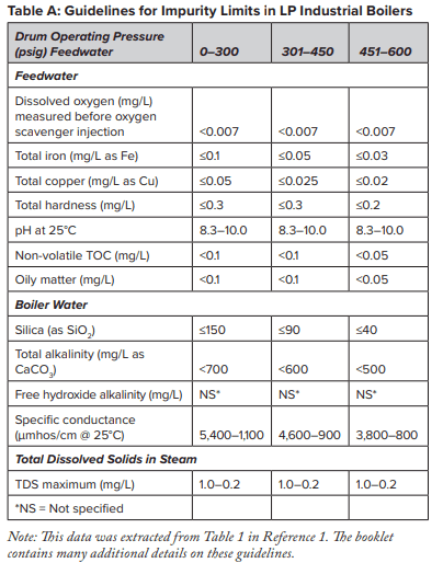
The data indicates that a significant amount of alkalinity can be tolerated in low-pressure boilers, and for many applications, some alkalinity may be desirable, as it helps protect metal surfaces from corrosion, a point we will return to later. However, HCO3, upon reaching the boiler, is in large measure converted to CO2 via the following reactions in Equations 2 through 4.
The conversion to carbon dioxide (CO2) from the combined reactions may reach 90%. CO2 flashes off with the steam, and when the CO2 re-dissolves in the condensate, it can increase the acidity of the condensate return.

Although the pH generated by this reaction has a relatively mild lower limit, the acidity is more than enough to cause significant carbon steel corrosion in condensate return systems. For example, 3 parts per million (ppm) of CO2 in pure steam condensate will lower the pH to 5.26. If dissolved oxygen is present in the system, corrosion can be greatly magnified.
A unit operation that can minimize production of CO2 in the steam generator is illustrated in the following fundamental diagram.
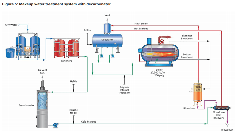
Note the inclusion of a forced-draft decarbonator with acid injection to the feed. The acid conditioning forces Equation 4 to the left, and a well-designed decarbonator can reduce the CO2 concentration to a low parts-per-million (ppm) level. Caustic feed downstream of the decarbonator then raises the pH of the water to make it less corrosive on its path to the boiler. Note: If steam attemperation is provided by direct injection of feedwater from the deaerator, then caustic cannot be used to raise the pH. A nonvolatile compound (e.g., ammonia, an amine) is required.
Another issue briefly hinted at above now requires a bit of discussion. With too-frequent regularity, when technical representatives begin visiting a plant for the first time, they find boilers with scale deposition, corrosion, or both. In many cases, plant personnel will reveal softener problems that have led to hardness breakthroughs. Equation 1 and Figure 2 illustrate the potential effects of such difficulties. But even a softener/decarbonator operating properly still allows many ions, such as chloride and sulfate, to enter the boiler. Without close attention to boiler water chemistry and boiler blowdown control, the accumulation of these ions can cause corrosion and other problems, including foam formation in boiler drums. This in turn can lead to steam contamination and downstream issues. To re-emphasize, steam generator makeup system and boiler water chemistry control require just as much attention as process operations.
Something Better Than Softening?
For modern makeup systems, reverse osmosis (RO) offers a reliable alternative to softening, where even basic systems can remove 99 plus percent of all ions from water. The osmosis process has been known for years. Two solutions of different concentrations, when separated by a semi-permeable membrane that only allows water to pass, will induce water in the dilute solution to move through the membrane to the other solution to balance the concentration. This phenomenon induces an osmotic pressure on the membrane until the solutions reach equilibrium. As the name reverse osmosis implies, the reaction is operated in reverse, and pressure produces purified water from a more concentrated stream.
The potential application of RO as a makeup water treatment method became well known in the last century and became popular with the development of and improvements to spiral-wound membrane technology.
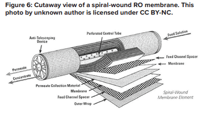
A flat membrane sheet has several layers as a backbone, which are all wrapped around a central, perforated plastic core. Feed enters the front end of each element and flows along the feedwater carrier while pressure pushes water through the membrane. The purified water, known as permeate, flows to the central core, and the increasingly concentrated feedwater (reject) exits the element.
Each RO pressure vessel typically has several elements arranged in a series.
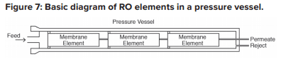
O-rings seal each element along the walls of the pressure vessel so that the feedwater does not short-circuit any of the elements. A typical RO pressure vessel will have five or six elements.
The configuration is designed to process the water via the mechanism known as crossflow filtration.
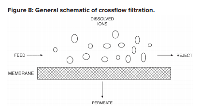
The feed flows parallel to the RO membranes, and pressure forces pure water through the membranes while the impurities are carried away with the reject. Only a few of the smaller monovalent ions (Na+, Cl-, silica, HCO3) pass through the membrane. However, while crossflow filtration is designed to keep impurities suspended in the reject stream, it is inevitable that even with exceptionally clean makeup, compounds will gradually build up on the membrane surfaces. Typically, residual suspended solids that are not captured by pretreatment will accumulate in the lead membranes of an RO system. Conversely, because dissolved ions concentrate as the water passes from one membrane to the next, scaling becomes an increasing concern in downstream elements.
The basic RO system is a two-stage, single-pass type, as outlined in Figure 9.
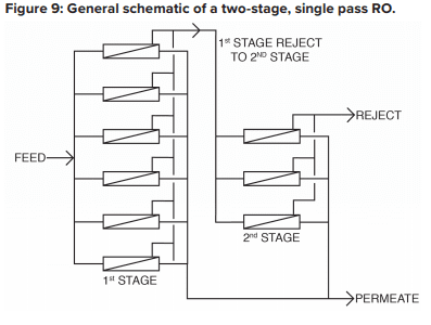
A critical feature of RO is illustrated in this diagram. With “normal” feedwaters, approximately 50% of the feedwater is converted to permeate in each first-stage pressure vessel. This means that without further processing, 50% of the feedwater would be wasted. In the two-stage design shown above, the raw feedwater flows through six parallel pressure vessels in the first stage, and the reject from these vessels is routed through three additional pressure vessels in the second stage. Total water recovery increases to 75%.
For some applications, especially those for ultra high-purity water production, two-pass RO is common. In this configuration, the permeate from the first pass is treated in a separate set of membranes. Because the feedwater has already been significantly purified, 85% to 90% recovery from the second pass is achievable. The reject is recycled back to first pass inlet, and no water is discharged to waste from the second pass.
RO has become quite popular for several applications in recent years, especially for steam-based power generating units. RO plus polishing mixed-bed ion exchangers or electrodeionization can produce the high-purity water needed for steam generation
RO Fouling and Scale Control
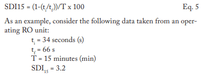
RO membranes, especially the lead elements, are susceptible to particulate fouling. An important measurement for determining this fouling potential is the silt density index (SDI). Usually, 5-micron (µm) depth filters are placed ahead of the RO to minimize the potential for particulate fouling. The SDI tests should be performed on the effluent from these filters. The SDI test is straightforward. A flowing sample of RO feedwater, downstream of the cartridge filters, is routed through a 0.45-µm filter at 30 psig pressure. Measurement is taken of the time for 500 milliliters (mL) of water to pass through the filter at the beginning of the test (ti) and again after 15 minutes (tf). The SDI is calculated as shown in Equation 5:
A general rule of thumb is that the SDI should be at least below 5 and preferably below 3. However, SDI should not be the only criteria that determines suitability of a RO application. The type of water and/or the nature of contaminants should also be considered. For example, in one application, the SDI readings of the RO feed always ranged between 1 and 3. Yet the membranes fouled with exceptionally fine iron oxide particles.
Scale formation is another issue that requires attention. When water flows through an RO pressure vessel, the concentrate continually accumulates dissolved solids, which increases the scaling potential. Calcium carbonate and sulfate can build up to a point where precipitation begins to occur. Other possible deposits include silica and alkaline metal silicates, strontium sulfate, barium sulfate, and calcium fluoride. While pretreatment can reduce the concentrations of many scale-forming compounds, the remainder may still cause problems. Barium and strontium sulfate scales are especially difficult to remove. Reputable membrane manufacturers have developed programs to calculate the solubility limits for these salts. The program will warn the user if any solubility limit is exceeded. The programs also provide “normalization” calculations of the RO system, as is described later.
Antiscalant feed is typical for RO systems. Common antiscalants include polyacrylates and phosphonates. The correct antiscalant or blend can control calcium sulfate at a factor of 7 above the saturation limit, strontium sulfate 800% above the saturation limit, and barium sulfate 6,000% above the saturation limit.
Pretreatment chemicals can affect membrane performance. Coagulating agents of the cationic variety and, most notably, aluminum compounds and some organic coagulants/flocculants, are particularly troublesome to RO membranes. If these agents are present, methods to remove them should be considered. Chlorine, usually introduced as bleach, injected into the primary plant makeup to control microbiological fouling will react with nitrogen atoms in RO membranes and irreversibly damage the materials. Chlorine should be removed upstream of the RO, but the absence of any biocides leaves the membranes in danger of microbial attack. Figure 10 shows how biofouling can damage a membrane element.
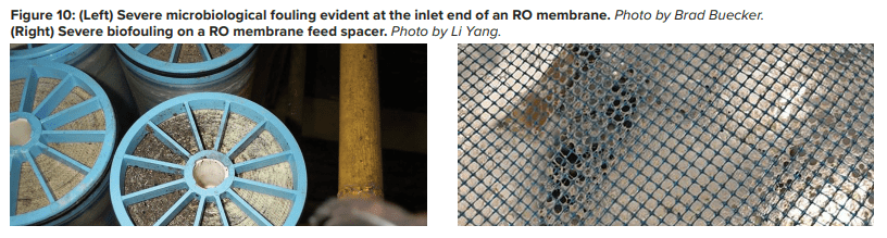
Biological fouling can cause irreversible damage to membranes because the deposits cannot be completely removed by standard cleaning methods. It is imperative to minimize conditions that can lead to microbiological deposition. Alternative techniques to chlorine are available to minimize microbe deposition within membranes. One is periodic treatment with a non- or mildly oxidizing biocide (frequency depends on fouling potential). A popular choice is dibromo-nitrilo-propionamide (DBNPA). A DBNPA chemical diagram is shown in Figure 11.
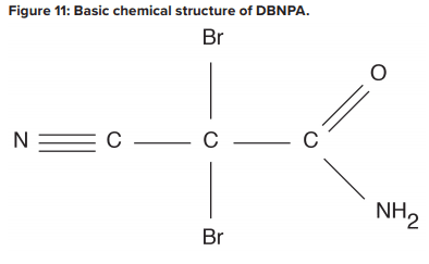
DBNPA is a fast-acting biocide that can be readily removed from any discharge by raising the pH to around 9, or commonly, treating with sodium bisulfite. Another possibility is a specialized version of chlorine dioxide (ClO2).A Such a product may sound surprising, as chlorine dioxide can act as a strong oxidizer in cooling water applications. However, in this case, the chlorine is not free, and thus does not react with nitrogen atoms in the membranes.
RO Cleaning
Even with well-controlled pretreatment and antiscalant chemistry, RO membranes will still collect deposits. The lead elements gather residual colloidal and suspended solids, while the downstream elements, especially those in the second stage, see higher concentrations of dissolved ions that may precipitate. Compounding the issue is that the pressure required to push water through the membranes can hold some of these particles in place. If impurities accumulate unchecked, the eventual result is irreversible membrane fouling.
Therefore, normalization programs are key for determining the need for and scheduling of RO cleanings. Temperature has a significant impact on permeate flux and pressure, and temperature changes can mask flow and pressure variations caused by suspended solids or scale buildup. Normalization programs use temperature, pressure, and flow measurements to provide corrected values for all temperature conditions. A common rule of thumb is to schedule a cleaning when the normalized value has dropped 10% to 15% from the baseline. Normalization programs can also help detect an increase in salt passage caused by a failed or degraded membrane, which might otherwise be attributed to temperature effects.
A two-step cleaning process is often employed to remove the potentially wide variety of foulants that can accumulate in RO membranes. Typically, in the first step, a high-pH (12 at 95°F) solution is circulated throughout the membranes. The alkaline solution removes organic compounds, microbiological and otherwise, that have accumulated. This stage is followed by a rinse and often a low-pH stage with citric acid as the key ingredient. Low pH helps remove soluble mineral salts such as calcium carbonate, while the citric acid will chelate metals, most notably iron. The inclusion of a heater in the cleaning loop can significantly speed up the process.
An important concept is to clean each stage separately. Otherwise, extracted impurities from one stage may foul the other, and vice versa. Also, cleaning systems are typically designed with cartridge filters in the cleaning loop to collect solids during the process. These filters should be replaced after each step in the cleaning.
The foregoing is general guidance only. Please consult your RO manufacturer for specific guidance.
RO Waste Stream Issues
As noted, a typical two-stage, single-pass RO system recovers approximately 75% of the inlet feed and produces a waste stream (reject) of the remaining 25%. This stream must be disposed somewhere. For plants with cooling towers, the basin of one of the towers is often an ideal location for the reject. Alternately, many plants have wastewater treatment facilities to condition discharge water before release to the environment. RO reject is basically plant makeup concentrated by a factor of four, so it should not overload the wastewater treatment equipment.
Makeup Water Treatment Issues Related to Boiler Water Treatment
A variety of treatment programs are available for low-pressure boilers, which may include phosphates, organic polymers, and sometimes chelating agents. These should be tailored to the chemistry of the water entering the boiler from both the makeup source and condensate return. A change from softened water to RO permeate can have a significant impact on boiler water treatment and even feedwater treatment. Higher purity waters are often known as “hungry” water because the lack of dissolved ions induces metals to give up ions to the water. Bicarbonate ions, even though they can react with calcium to form scale, will in many cases form a loose, protective layer on metals. For plant personnel considering a change from softened water to RO, these and other factors should be considered before making the switch. And, given that boilers should see a lower influx of hardness, the treatment program may need modification to account for this changed chemistry. A factor of major importance at many plants is the ratio of makeup water to condensate return. If the latter is much higher than the makeup flowrate, condensate return chemistry can dominate the selection of the best boiler water treatment program.

The post Keys to Reliable Makeup Water Treatment for Boilers appeared first on ChemTreat, Inc..
]]>The post Iron Monitoring in Industrial Steam Generating Systems appeared first on ChemTreat, Inc..
]]>By Frank Murphy, Ken Kuruc, and Brad Buecker
A previous issue of Water Technology outlined several important methods for improving water/steam chemistry in industrial steam generating networks to enhance equipment life and functionality.1 A partial extension of the earlier piece, this article shows how condensate and feedwater iron monitoring can alert operators and technical personnel to corrosion issues and can be used to optimize chemical treatment programs. For high-pressure steam generators that produce power and have high-purity makeup and feedwater, iron monitoring is valuable for evaluating a specific phenomenon: flow-accelerated corrosion.
You can read the rest of the article online here.
The post Iron Monitoring in Industrial Steam Generating Systems appeared first on ChemTreat, Inc..
]]>The post Take Better Care Of Your Low-Pressure Boiler appeared first on ChemTreat, Inc..
]]>By Brad Buecker and Chad Frierson
Many plants use low-pressure boilers to produce process steam for various applications, including heat for chemical reactors, evaporators, building spaces, etc. Often, sites pay less attention to the chemistry programs for these steam generators than to those for high-pressure units. Yet, contaminated condensate return, malfunctions of makeup water treatment systems, and other factors can cause many problems.
The post Take Better Care Of Your Low-Pressure Boiler appeared first on ChemTreat, Inc..
]]>The post The Challenges of Industrial Boiler Water Treatment appeared first on ChemTreat, Inc..
]]>This article was originally published in PPCHEM® Journal; PPCHEM® 2020, 22(6), 252–259; https://journal.ppchem.com/
Abstract
High-pressure steam generators for power production require high-purity makeup and feedwater and controlled boiler water chemistry to minimize corrosion and scale formation in the boilers, superheater/reheater circuits, and turbines. Numerous articles in the PPCHEM® journal over the last two decades have outlined these chemistries and their evolution.
However, while many heavy industries have high-pressure steam generators for co-generation needs, these plants and many other smaller facilities also have low-pressure boilers that produce process steam. The lower heat fluxes and pressures in these steam generators somewhat alleviate the stringent treatment requirements necessary for high-pressure units but offer more complexity in the choice of optimum treatment methods.
This article provides an overview of modern methods for protecting lower-pressure steam generators from factors that typically do not plague their high-pressure counterparts.
Introduction
High-pressure steam generators for power production require high-purity makeup and feedwater and controlled boiler water chemistry to minimize corrosion and scale formation in the boilers, superheater/reheater circuits, and turbines. However, while many heavy industries have high-pressure steam generators for co-generation needs, these plants and many other smaller facilities also have low-pressure boilers (boilers of less than 4.14MPa (600psig)) that produce process steam. The lower heat fluxes and pressures in these steam generators somewhat alleviate the stringent treatment requirements necessary for high-pressure units but offer more complexity in the choice of optimum treatment methods. Potential issues such as contaminated condensate return and makeup water treatment system malfunctions can increase the complexity of steam generation water/steam treatment.
This article provides an overview of modern methods for protecting lower-pressure steam generators from factors that typically do not plague their high-pressure counterparts.
The Complexities of Makeup, Condensate Return, and Feedwater Chemistry
In utility systems, the steam is condensed and returned to the boiler after performing its work in the turbine. The complete water/steam circuit is nearly a closed loop with approximately 0.5–2% water loss and corresponding makeup additions. Mature technologies such as reverse osmosis (RO) and ion exchange are available to produce high-purity makeup (≤2μg∙L–1 of sodium and chloride, ≤10μg∙L–1 of silica, and ≤0.1μS∙cm–1 specific conductivity). In the absence of a condenser tube leak or, less frequently, makeup system upset, the feedwater remains highly pure on its path to and through the steam generator and turbine, and for that small portion utilized for steam attemperation.
Now consider the realm of low-pressure steam generation, where the boilers do not require demineralized makeup. For decades, and even today, sodium zeolite softening has been a common primary treatment method for industrial boiler makeup. In this process, the makeup passes through a bed of ion exchange resin that trades calcium and magnesium hardness ions for sodium. The softened stream, with the remaining impurities including bicarbonate alkalinity (HCO3–), chloride (Cl–), sulfate (SO42–), silica (SiO2), and others, then feeds the boiler. Some softening makeup systems include a splitstream de-alkalizer, or perhaps a forced-draft decarbonator, to remove most of the alkalinity. This can be beneficial, as will be outlined.
Basic softening offers both advantages and drawbacks. Compared to complete demineralization, softening saves plants money in equipment and operating costs. Regenerating softening resins with brine is straightforward and does not require storing and handling dangerous acids and caustic. The major difficulty with softening is that the ions not removed by the process can become problematic upon reaching the steam generator. Alkalinity is a prime example. If it is not removed from the makeup, alkalinity will at least partially convert to carbon dioxide (CO2) in the boiler, carrying over with the steam. Upon steam condensation, the CO2 can lower the pH, leading to potential condensate corrosion issues for carbon steel piping.
The introduction of other water impurities to the boiler can lead to higher conductivity, increasing the general corrosion potential of the water, especially because the ions “cycle up” in drum boilers as steam is produced. While some accumulation of these impurities is tolerable, in many cases, plant personnel do not track deposit buildup in boilers, particularly of iron oxide corrosion products transported from elsewhere, e.g., condensate return systems. Boiler water impurities can concentrate under these deposits to much higher levels than in the bulk water, and induce under-deposit corrosion.
Heavy deposits also restrict heat transfer, and in areas of high heat flux may lead to tube overheating and mechanical failure as shown in Figure 1, where iron oxides from condensate return created thick deposit layers followed by fishmouth opening of the tube from overheating [1].
RO technology offers a reliable option for producing makeup water with very low dissolved solids. At many power plants, RO serves as the primary demineralization step with mixed-bed ion exchange or continuous electrodeionization (CEDI) polishing as the final stage, but RO as a stand-alone process can suffice for many low-pressure boilers. The process removes the bulk of impurities (often 99% or more), including silica, which can allow for higher boiler water cycles of concentration, thus saving costs via reduced makeup and blowdown.
Sufficient pretreatment to remove suspended solids ahead of RO membranes and a well-designed chemical treatment program to minimize scale formation are important to successful RO unit operation. Careful RO feedwater analysis is critical for proper pretreatment equipment and chemical selection. Also, RO generates a nearsteady wastewater stream that must be disposed of. For plants with cooling towers, the tower basin may serve as a good repository. Otherwise, alternative disposal methods may be needed.
There are many examples of makeup system upsets wherein plant personnel operated the systems in failed mode or sometimes even bypassed malfunctioning systems and fed raw water to the boiler. A mindset of “water is water” seems to prevail in these cases. Such assumptions can lead to disastrous consequences, and boiler tubes have been known to fail within days or sometimes hours of such decisions.
Feedwater and Condensate Return Issues
Apart from whatever method is utilized for makeup water production, significant impurities can enter the steam generator via condensate return from plant processes. The percent condensate return may range from slight to very large depending on plant design and operation. In a classic example of contaminated condensate observed years ago by one of the authors, superheater bundle replacement of four package steam boilers at an organic chemicals plant was required every 1.5–2 years because of internal deposition and overheating failures. The root cause was excessive organic ingress to the condensate return, which induced foaming in the boiler drums and solids carryover to the superheaters. No systems were in place either to polish the condensate or to dump it during impurity excursions.
Depending on the chemical processes at the plant and the ability of impurities to enter the condensate, a wide variety of contaminants can potentially enter the boiler. A program should be in place to detect chemical leakage from heat exchangers, reactors, or other vessels, and to make repairs as needed. Testing condensate return for pH, hardness, and specific conductivity is common. And, it might be prudent to check the return condensate for organics in specific cases. With such monitoring, the condensate can be diverted to drain if the measurement exceeds a predetermined limit, e.g., 50μS∙cm–1 continuous on-line conductivity. Setpoints for dump or reuse of return condensate should be defined for all site-specific parameters that might impact boiler feedwater quality. Condensate dumping can be expensive considering the costs for makeup water production and heating water to produce steam; however, plant personnel may rely too much on the boiler water treatment program to alleviate problems. Excessive contamination can overload any treatment program.
As with high-pressure steam generators, establishing and maintaining a moderately basic pH range (in general, pH 9–10) is an important issue for feedwater and condensate return systems in low-pressure units to prevent general carbon steel corrosion. In the power industry, the common pH conditioner is ammonia, which raises feedwater pH via the following reaction:

This is a reversible reaction, so the alkalinity increase is limited, which usually minimizes excessive steel corrosion in the event of a chemical feed upset. (High ammonia concentrations, especially in the presence of oxygen, can be very detrimental to copper alloys.) Conditions are often different in low-pressure boilers. If the makeup water is sodium-softened only, sufficient alkalinity may be present to maintain a basic pH. Sometimes a bit of caustic feed may be employed to boost feedwater pH, although care must be taken when using this strong chemical.
However, the wild card for industrial systems is condensate return, in which the pH may be significantly depressed by carbon dioxide carryover. Accordingly, neutralizing amine injection to condensate return is often employed to minimize corrosion in carbon steel piping networks.
A common injection point is the storage section of the deaerator or directly to the steam header, which may be better. The chemical or chemical blend not only protects the condensate but carries through the system. Table 1 details several of the most common neutralizing amines.
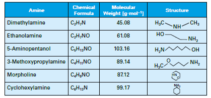
Table 1: List of common neutralizing amines.
The amines all have a higher molecular weight than ammonia, and thus will not flash off as readily, although each has its own distribution ratio (the amount remaining in the water vs. that departing with steam) whose properties are a function of temperature and pressure. The products also have different basicities, providing flexibility in treatment program selection. Careful evaluation of condensate return system operating and design conditions is necessary to select the most appropriate amine or amine blend.
Some compounds are not allowed if the steam can directly contact food or other consumable products.
As discussed in a previous issue of the PPCHEM® journal, monitoring total iron concentrations in condensate is highly recommended to evaluate feedwater chemistry efficacy [2]. We will return to this idea again later in this article.
Dissolved Oxygen Control
In the middle of the last century, the consensus about dissolved oxygen (DO) in boiler feedwater was uniform: oxygen should be eliminated because it is highly corrosive. But European and Russian researchers in the late 60s and early 70s discovered that some dissolved oxygen (at concentrations up to 300μg·L–1) introduced to high-purity water during normal operation induced formation of a tight α-hematite oxide layer on carbon steel piping. Corresponding particulate and dissolved feedwater iron concentrations could be driven to very low values of 1μg·L–1 or even less. The program became known as oxygenated treatment (OT) and was widely applied to once-through supercritical units in Europe and, eventually, in the United States and elsewhere. The caveat for OT is that it requires exceptionally high-purity feedwater (≤0.15μg·L–1 cation conductivity); otherwise, oxygen corrosion may occur. Figure 2 illustrates this concept.
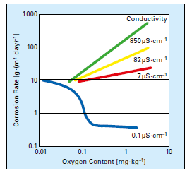
Figure 2: Oxygen corrosion rates as a function of dissolved solids content. [3]
Drum units continued to operate with feedwater chemistry anchored to dissolved oxygen removal by mechanical deaeration and reducing agent (also known as oxygen scavenger) treatment until failures from flow-accelerated corrosion (FAC) began to emerge in the 1980s. A number of these failures caused injuries and fatalities at power plants over the next three decades. FAC chemistry has been well documented in the PPCHEM® journal [4] and other publications, but a key point is that it led to the development of a cousin to OT for drum units named all-volatile treatment, under oxidizing conditions (AVT(O)), which also relies on a small concentration of dissolved oxygen in the feedwater. AVT(O) also requires high-purity feedwater (≤0.2μg·L–1 cation conductivity) to develop the proper oxide layer on carbon steel while minimizing oxygen corrosion.
The upshot of this brief discussion about OT and AVT(O) is that industrial boilers are usually supplied with less than high-purity makeup, and often recover condensate that contains some impurities, so neither AVT(O) nor OT can be utilized because of the potential for severe oxygen corrosion of carbon steel components. Most industrial feedwater systems are equipped with mechanical deaerators, which, when operating properly, should reduce the DO concentration to 7–10μg·L–1. A common layout for industrial low-pressure steam generation is displayed in Figure 3.
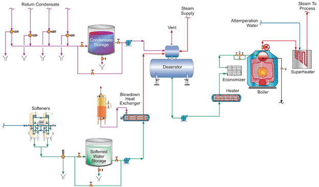
A chemical reducing agent is also typically employed to further lower DO levels. For steam generators at or below a pressure of 4.14MPa (600psi), either un-catalyzed or catalyzed sodium sulfite (Na2SO3) is a popular reducing agent. This non-volatile oxygen scavenger adds some inorganic dissolved solids to the feedwater.

A common injection point is the deaerator storage tank.
But as has already been observed many times in the power industry, complete DO removal leads to conditions that promote FAC. This raises an important question, “Can FAC occur in industrial feedwater systems if the DO concentration is reduced to very low values?” The answer is yes, and reference [5] outlines mild cases of FAC at a co-generation facility in the United States. To summarize, recent non-destructive testing revealed some wall loss at elbows on both the suction and discharge side of several boiler feedwater pumps as well as at a nozzle and a weld seam. None require immediate repair, but they prompted plant personnel to plan additional testing to ensure other locations are not seriously damaged. Undoubtedly, a mitigating factor in the mild nature of those spots suffering from FAC is that plant personnel have strived to maintain feedwater pH within a mid- to upper-9 range, in accordance with data presented by Sturla [6] nearly five decades ago (Figure 4).
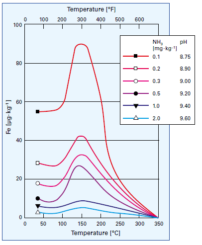
Figure 4: Influence of temperature and pH on iron dissolution from carbon steel [5]. The temperature aspect is why FAC is typically most pronounced in the feedwater systems and economizers of many conventional steam generators and the LP evaporators of multi-pressure heat recovery steam generators (HRSGs).
An important point to note is that this elevated pH range would be too high for most systems containing copper alloys and would need to be lowered to the low 9s for combined iron and copper corrosion control. It is in such situations that analytical techniques like corrosion product sampling can be quite valuable, where the solution concentration of both metals can be evaluated. For all-ferrous systems, straight iron monitoring techniques are possible, and reference [1] outlines several of these techniques. The International Association for the Properties of Water and Steam (IAPWS) has generated a Technical Guidance Document (TGD) [7], which discusses the variety of analytical methods that can be used for these tests. At the facility highlighted in reference [5], personnel make spot checks of condensate and feedwater iron concentrations via the well-known Millipore test method, in which a known volume of the sample is passed through a very small-pore (0.45μm) white filter paper, whose color is compared to standard samples after drying. The Millipore procedure was in large measure pioneered and promoted years ago by the boiler manufacturer Babcock & Wilcox for quick calculations of feedwater iron concentrations during unit startups [8]. In utility boilers, virtually all of the particulates will be iron oxides, but in industrial steam generators with complex steam and condensate return networks, other impurities that mask the results may exist.
In many complex industrial steam generation/condensate return systems, it is desirable to have proper pH control throughout the network, but a single compound may not be sufficient to achieve this control. The authors’ colleagues have developed blended amine products that can provide wide-ranging coverage. A thorough analysis of system design, metallurgy, current chemistry, and operating temperatures is a prerequisite for proper program selection.
Film-Forming Chemistry for Corrosion Protection
Film-forming amines (FFA) were introduced by the water treatment industry decades ago, and recent years have seen a re-emergence of film-forming substances (especially octadecylamine or C18H39N) for corrosion protection. The amine group on each molecule attaches to the metal substrate, and the long-chain organic portion of the molecule extends into the water and acts as a barrier. However, poor control and lack of detailed knowledge of the overall chemistry have often led to problems, including formation of “gunk balls” that fouled steam generators [9]. Advancements in chemical synthesis techniques and analytical instrumentation have led to the development of new film-forming substances, both amines and other compounds, that are much more effective at protecting metal surfaces. This includes the FFA products of ChemTreat’s TITAN360 series. Figure 5 shows a protected metal surface (during off-line conditions). Note how the water beads rather than wetting the surface.
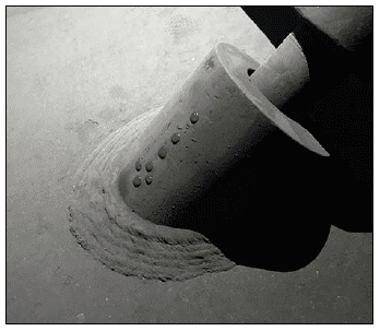
Figure 5: Protected metal surface with FFA.
When correctly applied, film-formers can protect metal surfaces during normal operation and unit downtimes. However, it must be noted that implementing FFA programs requires proper system oversight and control. Less-than-knowledgeable vendors have been known to suggest that such chemicals could be injected into the unit, after which corrosion issues would magically disappear. Severe problems were the result instead. A careful analysis of system operation and past/present chemistry is necessary beforehand, with careful monitoring and control required after FFA chemistry is introduced, as it is explicitly described and recommended in section 8 of the IAPWS TGD11-19 [9].
Boiler Water Treatment
In the 1930s, as power generating units increased in number and size, tri-sodium phosphate (Na3PO4, also known as TSP) became a popular boiler water conditioning chemical for drum boilers. At that time, phosphate treatment served two primary functions. The first was to establish moderately alkaline conditions in the boiler to minimize general corrosion of carbon steel boiler tubes, drums, and headers.

This function is still quite critical today.
A second function of phosphate was, and in many cases still is for industrial boilers, important for scale control where hardness ingress occurs. Eq. (4) below outlines the most common of these scale-forming reactions, which has probably been observed ever since humans began heating water for personal and then industrial use.

Calcium carbonate (CaCO3) deposition, often accompanied by other minerals, still plagues many industrial steam generators when makeup systems malfunction but remain in operation or are bypassed.
Phosphate and the alkalinity produced by its reaction with water will react with hardness ions to form soft sludges as opposed to hard scale. However, in the early days of power unit operation, some boilers were plagued by under-deposit caustic corrosion generated by the rather high concentrations of TSP needed for scale control. This led to the development of coordinated and congruent phosphate treatment programs that utilized blends of tri-, di-, and sometimes even a small amount of monosodium phosphate. Subsequent research has shown that these chemistries can generate acidic phosphate deposits in high-pressure steam generators. Utility boiler treatment programs have returned to TSP (or, in some cases, caustic treatment), albeit in low dosages of perhaps no greater than 2mg·L–1. This is possible because modern makeup treatment systems are quite reliable, such that hardness in-leakage is very rare. Thus, phosphate treatment is used for pH control only.
For industrial boilers, phosphate treatment remains a strong choice, particularly because the potential for hardness ingress to many industrial units is much greater. The lower heat fluxes in these steam generators allow higher phosphate dosages than in utility units. And it may be possible to sometimes employ phosphate blends rather than TSP alone for more flexibility in pH control. Sludge conditioners consisting of water-soluble polymers that help keep solids in suspension by a combination of dispersion, crystal modification, and sequestration are often recommended alongside phosphate treatment. Iron particulates from condensate return system corrosion can be problematic, but sludge conditioners help to keep the particles in suspension for subsequent blowdown. These polymers can sometimes serve as a standalone treatment, particularly if hardness ingress is not an issue.
In former days, chelants were sometimes employed in industrial drum units. These chemicals directly bind with metals to keep them suspended. Ethylenediaminetetraacetic acid (EDTA) is the most widely known chelant and has been used for many applications both inside and outside industrial applications. However, improper chelant use can cause localized corrosion of boiler components. Chelant programs are very rare now and should only be used with well-deaerated feedwater, excellent pretreatment control, and low feedwater iron concentrations.
The upshot is that several possibilities, namely phosphate/polymers, polymers alone, and, rarely, chelating agents, exist for boiler water treatment, but the proper choice depends on a variety of factors that include boiler design and pressure, makeup water treatment sophistication and reliability, and the potential for impurity ingress and iron oxide carryover from condensate return. These factors must be evaluated carefully for each case. A “one size fits all” approach to treatment selection can lead to problems.
Conclusion
The lower pressures and heat fluxes in industrial steam generators make them less susceptible to high-temperature corrosion mechanisms than those in utility units. However, chemical treatment of these lower-pressure units may be more complicated because of several factors, including:
- The potential for impurity ingress from complex steam feed and condensate return systems.
- Inadequate attention to makeup water treatment system performance, which allows unwanted impurities such as hardness to enter boilers.
- Condensate return system corrosion that not only damages system piping and equipment but sends iron oxide corrosion products to the boiler. These particulates tend to deposit in high-heat locations, subsequently reducing heat transfer and establishing sites for under-deposit corrosion and overheating failures because of insufficient tube wall cooling.
Careful planning is necessary to establish the proper treatment programs for the entire steam generation system and condensate return networks. A variety of methods are available to optimize chemistry. Comprehensive monitoring is necessary to ensure treatment programs are performing as intended.
Acknowledgement
The authors would like to greatly thank Frank Udo Leidich of the PPCHEM® journal International Advisory Board for reviewing this article and providing valuable information.
References
[1] Bursik, A., “Boiler Tube Failures in Industrial Drum-Type Steam Generators – Part 1: Feedwater Treatment and Under-Deposit Corrosion Failures”, PowerPlant Chemistry 2001, 3(8), 459.
[2] Buecker, B., Kuruc, K., “Sampling Points and Parameters for Low-Pressure Industrial Steam Generators”, PPCHEM 2020, 22(4), 142.
[3] Feed Water, Boiler Water and Steam Quality for Power Plants / Industrial Plants, 2011. VGB PowerTech Service GmbH, Essen, Germany,
VGB-S-010-T-00;2011-12.EN.
[4] Dooley, B., Tilley, R., “Tube Failures in Conventional Fossil Plants and in HRSGs”, PowerPlant Chemistry 2001 3(12), 703.
[5] Buecker, B., Murphy, F. P., Breakdown: Is Flow-Accelerated a Concern in Co-Generation Steam Generators? Available from https://www.power-eng.com.
[6] Sturla, P., “Oxidation and Deposition Phenomena in Forced Circulating Boilers and Feedwater Treatment”, presented at the Fifth National Feedwater Conference, 1973 (Prague, Czechoslovak Socialist Republic).
[7] Technical Guidance Document: Corrosion Product Sampling and Analysis for Fossil and Combined Cycle Plants, 2014. International Association for the Properties of Water and Steam, IAPWS TGD6-13(2014). Available from http://www.iapws.org.
[8] Membrane Filter Comparison Charts – Procedures and Test Methods, 1964. The Babcock and Wilcox Company, Barberton, OH, USA.
[9] Technical Guidance Document: Application of Film Forming Substances in Industrial Steam Generators, 2019. International Association for the Properties of Water and Steam, IAPWSTGD11-19. Available from http://www.iapws.org.
The Authors
Brad Buecker (B.S., Chemistry, Iowa State University, Ames, IA, USA) is a senior technical publicist with ChemTreat. He has many years of experience
in or affiliated with the power industry, much of it in steam generation chemistry, water treatment, air quality control, and results engineering
positions with City Water, Light & Power (Springfield, IL, USA) and the Kansas City Power & Light Company’s (now Evergy) La Cygne, KS, USA, generating station. Most recently he was a technical specialist with Kiewit Engineering Group Inc. He is a member of the American Chemical Society, American Institute of Chemical Engineers, American Society of Mechanical Engineers, Association of Iron and Steel Technology, National Association of Corrosion Engineers, the Electric Utility Chemistry Workshop planning committee, the International Water Conference Advisory Council, and the Power-Gen International planning committee. Mr. Buecker has authored many articles and three books on power plant topics.
Tim Hughes (B.S., Petroleum and Natural Gas Engineering, Pennsylvania State University, State College, PA, USA) is a senior technical staff consultant with ChemTreat. He has 29 years of industrial water treatment experience and 8 years of oil & gas experience. He previously held positions at Betz Laboratories, Universal Well Services and National Fuel Gas Supply Corp.
Request ConsultationThe post The Challenges of Industrial Boiler Water Treatment appeared first on ChemTreat, Inc..
]]>The post Protecting Water/Steam Chemistry appeared first on ChemTreat, Inc..
]]>By Brad Buecker, Senior Technical Publicist
During much of the last century, many central power stations came on-line to satisfy the rapidly growing need for electricity in the post-WWII United States. Large power stations were a wonder of technology at the time, and I began my career at one of these plants in the early 1980s. However, even as people marveled at these facilities and their intricacies, it came to be recognized that the net thermodynamic efficiencies of these plants were low, with a mid-30 percent range for subcritical drum units, and at most mid-40 percent for even advanced supercritical units.
Click here to read more.
The post Protecting Water/Steam Chemistry appeared first on ChemTreat, Inc..
]]>The post Sampling Points and Parameters for Low-Pressure Industrial Steam Generators appeared first on ChemTreat, Inc..
]]>This article was originally published in PPCHEM® Journal; PPCHEM® 2020, 22(4), 142–150; https://journal.ppchem.com/
Abstract
Although thousands of low-pressure steam generators exist at industrial plants around the globe, the chemistry of such units has not received the same attention as that of high-pressure units. The conditions in these steam generators are typically not as harsh as in utility units, yet water/steam chemistry control is still very important for the plants’ steam/condensate systems. This article discusses many of the most important sampling points and parameters for industrial steam generators, and it illustrates the benefits of proper chemistry control to maintaining equipment reliability and availability.
Introduction to Sampling Points and Parameters for Low-Pressure Industrial Steam Generators
For over two decades, the PPCHEM® journal has offered informative articles from world-class experts on high-pressure steam generation chemistry. The knowledge provided has been of great benefit to many power plant chemists and technical personnel. However, the contributors of this article recognize that thousands of low-pressure steam generators exist at industrial plants around the globe. Even though conditions in these steam generators are typically not as harsh as in utility units, water/steam chemistry control is still very important. Yet, the authors have frequently observed that some industrial plant owners, operators, and technical personnel focus on process engineering and chemistry, rather to the neglect of the plant’s steam/condensate systems. This article outlines many of the most important sampling points and parameters for industrial steam generators, and it illustrates the benefits of proper chemistry control to maintaining equipment reliability and availability.
Industrial Steam Generating Circuitry
Figure 1 below illustrates a general schematic of a common industrial steam generation/condensate return system. Obviously, any number of alternatives or nuances to this arrangement may exist depending upon the nature of the products generated and required conditions of the steam. However, the schematic provides a good foundation for this discussion. In this article, the authors will mostly consider steam generators less than 4.14MPa (600 psig) in pressure.
The following text progresses through the numbered sample points, with some commentary about the evolution of chemical treatment advancements that offer improvement over former technologies. An important point to note in the diagram and in the discussion below is that continuous sampling is recommended at several locations. Continuous water/steam chemistry monitoring is, of course, important for high-pressure/temperature power generating units, but even in these lower pressure systems some upsets can cause serious damage in short order which cannot be detected in a timely manner with grab sampling alone.
In order to gain pertinent and valuable information from the sample taken, one must be certain that the sample obtained is representative of the species within the loop. This is true both for grab samples and with on-line monitoring. Especially of concern is the requirement that the velocity of the fluid entering the sample nozzle port be exactly the same as the velocity of the stream being sampled, otherwise known as isokinetic sampling. The International Association for the Properties of Water and Steam (IAPWS) has generated a technical guidance document (TGD) which addresses the challenges of making these measurements [1].
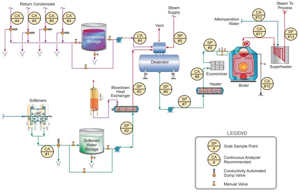
Figure 1. General schematic of recommended sample points for industrial process steam flow and condensate return.
Makeup System Effluent Quality #1
A quite common makeup system design at many plants, at least in the United States, has relied on sodium softening of the inlet plant water, whose source is often municipal potable water. These makeup supplies are generally free of suspended solids (except perhaps those picked up by some corrosion of carbon steel pipes), and primarily contain the dissolved ions from the original source. Often, a significant portion of the hardness has already been removed at the water plant via lime softening. However, even these waters, although suitable for drinking, require further treatment for hardness removal. Eq. (1) below outlines the most common scale-forming mechanism that can occur in steam generators unless hardness is reduced.
Ca2+ + 2HCO3– + heat → CaCO3↓ + CO2 + H2O (1)
Calcium carbonate (CaCO3) is inversely soluble with temperature, and thus solutions containing calcium and bicarbonate alkalinity, which may be fine at ambient conditions, can cause significant scaling in hot water systems, boilers, and other heat exchangers (see Figure 2).
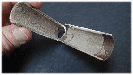
Figure 2. Calcium carbonate scale in a heat exchanger tube.
One of the authors was once employed at a chemical plant where the incoming makeup was split into two streams, one with sodium softening treatment for part of the manufacturing process and the other with reverse osmosis (RO) followed by cation and anion exchange polishing for high-purity needs. To ensure reliable output from the softeners, plant personnel installed a continuous calcium monitor on the softener effluent, whose detection limit was 1μg·L–1.
Even a softener that is well maintained and operated still allows the other ions in the makeup to reach the boiler, and these may cause difficulties.
For example, bicarbonate alkalinity, upon reaching the boiler, is in large measure converted to CO2 via the following reactions (Eqs. (2) and (3)):
2HCO3– + heat → CO32– + CO2↑ + H2O (2)
CO32– + heat → CO2↑ + OH– (3)
The total conversion of CO2 from the combined reactions may reach 90%. CO2 flashes off with the steam, and when the CO2 re-dissolves in the condensate it can increase the acidity of the condensate return.
CO2 + H2O ⇔ H2CO3 ⇔ H+ + HCO3– (4)
Although the acidity generated by this reaction has a relatively mild lower limit (minimum pH above 5), it is more than enough to cause significant corrosion of carbon steel in condensate return systems. If dissolved oxygen is present, corrosion can be greatly magnified.
Other impurities that can enter the steam generation system with sodium softening as the only makeup treatment include chloride and sulfate salts, and silica. These compounds can potentially influence corrosion and steam purity. As a result of the development of reliable membrane-based technologies, RO offers a solid alternative and upgrade to softening, where even basic systems can remove 99% of all ions from water. Analytical instrumentation for RO units is typically included with the system as outlined in Figure 3.
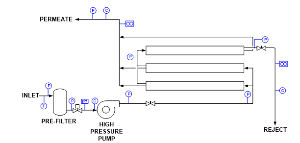
Figure 3. Common RO instrumentation.
T = temperature
P = pressure
C = specific conductivity
Instrument outputs can be connected to both local and distributed control system (DCS) networks for monitoring and operational purposes. Alarms and, if necessary, automatic unit shutdown are possible for a number of conditions. Some of the most important include [2]:
- Low inlet pressure
- High/low pH
- High temperature
- High permeate pressure
- High permeate conductivity
- Low concentrate flow
Another measurement that can be beneficial upstream of an RO unit is oxidation-reduction potential (ORP) to protect the membranes from an excursion of an oxidizing biocide, which could cause severe damage.
Makeup to the Deaerator (#2 and #3)
Only grab sample analyses are shown for these sampling points, as under normal conditions the chemistry should not change from that produced by the makeup water treatment system. On occasion, however, makeup storage tanks have become contaminated from unusual circumstances. Figure 1 also shows a heat exchanger to recover energy from the boiler blowdown. These exchangers are not always present. If an exchanger develops a leak, the boiler blowdown will be of worse quality than the makeup and will contaminate the feedwater.
Condensate Return (#4)
For the following discussion of sample point 4 (and also #6 through #10), Table 1 is a good guide. It outlines data extracted from [4], which has been a long-term guide to water quality limits for industrial boilers in the United States.
Given the enormous variety of products that come from chemical plants, refineries, steel mills, acid production facilities, and others, multiple impurities from leaking heat exchangers or reaction vessels could be present in condensate return. A classic case history comes from an organic chemical plant that one of the authors and a former colleague visited a number of years ago. The superheaters of four 3.79MPa (550 psig) package boilers had to be replaced every 1.5 to 2 years due to excessive deposition and overheating. An initial walkaround revealed foam exiting from the saturated steam sample line of each boiler. A review of water chemistry data provided by an outside vendor indicated total organic carbon (TOC) concentrations in the condensate return as high as 200mg·L–1. Contrast this value with the 0.05mg·L–1 feedwater limit recommended in Table 1. The high organics caused severe foaming in the boiler drums and carryover of compounds to the steam. Unlike the layout shown in Figure 1, the condensate return had no on-line instrumentation and no automatic dump system to discard contaminated condensate.
Depending upon the potential impurity ingress to the condensate return, a number of different instruments might be suitable for monitoring condensate return. Specific conductivity and cation conductivity (now often designated as conductivity after cation exchange (CACE)) come quickly to mind, as they can provide a general indication of contamination, with CACE helping to account for the influence of ammonia or neutralizing amines utilized to adjust pH (additional discussion of pH monitoring and control is included below). For the case history mentioned above, TOC analyses could have been beneficial. An additional application where TOC analyzers can be valuable is on the steam/condensate systems at liquified natural gas (LNG) import and export facilities. Yet another potentially very useful analytical measurement at refineries, petrochemical plants, and such is oil-in-water [5]. Many sources of oil or hydrocarbon ingress to condensate (and cooling water) are possible at these facilities.
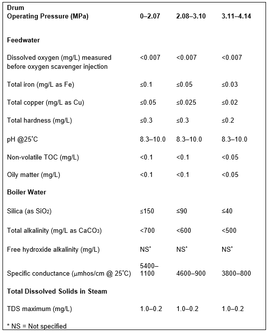
Table 1. Guidelines for impurity limits in low-pressure industrial boilers. This data was extracted from Table 1 in Reference 3. The booklet contains many additional details regarding industrial boiler water guidelines.
Deaerator Inlet Steam (#5)
A sample tap on this line allows periodic checks of steam purity to the deaerator. However, the steam supplied to the deaerator will be extracted from the main steam, whose recommended analyses are outlined later in this article. With that instrumentation in place, sampling of #5 should not normally be required.
Boiler Feedwater (#6 to #9)
Many articles have appeared in the PPCHEM® journal and elsewhere over the last several decades about feedwater chemistry for high-pressure steam generators and the need to minimize flow-accelerated corrosion (FAC) [6]. For those units that do not have any copper alloys in the condensate/feedwater system, treatment chemistry has evolved to either all-volatile treatment oxidizing (AVT(O)) or oxygenated treatment (OT), where the presence of some oxygen is required to generate the correct oxide layer on carbon steel surfaces. However, AVT(O) and especially OT require high-purity makeup water (CACE < 0.2μS·cm–1 for AVT(O) and <0.15μS·cm–1 for OT), as otherwise serious oxygen corrosion will result. This is a luxury not common at many industrial facilities. Accordingly, a well-maintained and -operated deaerator is a critical component of the feedwater network. As is common with utility steam generators, Figure 1 shows continuous analysis at the economizer inlet #8. One of these measurements is, of course, dissolved oxygen (DO). A properly operating deaerator should reduce dissolved oxygen concentrations to 7μg·L–1. Supplemental chemical oxygen scavengers/reducing agents may be utilized to lower the DO concentration even further. Use of a portable DO meter at sample points #6 and #7 can help to confirm on-line readings, or to troubleshoot air ingress at the boiler feed pumps. Continuous DO analysis of sample #8 is also recommended.
Note: Sample point #9 is an even better location than #8, but in the authors’ experience this sample point, the economizer outlet, is often not available.
However, a question that can be justifiably posed is, “Can FAC also occur in industrial feedwater systems, particularly if dissolved oxygen is reduced to very low levels?” The answer is yes, but in many cases AVT(O) or OT are not acceptable due to higher-than-allowed dissolved solids (for these programs), which are often present in industrial boiler makeup and feedwater. Research and operation in utility units has shown that pH has a strong influence on FAC, and so FAC control can in large measure be approached in that regard.
Guidelines developed by the Electric Power Research Institute (EPRI), the International Association for the Properties of Water and Steam (IAPWS) and others recommend a feedwater pH above 9.0, and typically at least in a mid-9 range, for power plant units. Steel corrosion is greatly reduced at these alkalinity levels. While Table 1 suggests a pH range of 8.3–10.0 for industrial boilers, the lower limit can probably be raised, preferably towards the ranges recommended for power units and indicative of the data shown in Figure 4.
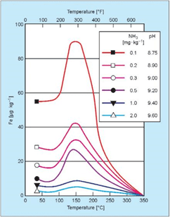
Figure 4: Influence of pH and temperature on iron dissolution from carbon steel [3].
In the power industry, the common feedwater pH-conditioning chemical is ammonia, which elevates pH via the reaction shown in Eq. (5):
NH3 + H2O⇔NH4 + OH– (5)
Ammonia addition to water is an equilibrium reaction and thus the pH increase is limited. But ammonia is quite volatile, and the compound significantly partitions with steam in low-pressure boilers. For industrial units, neutralizing amines are a common alternative to ammonia for feedwater pH conditioning.
Developing the best program for comprehensive system protection has sometimes been difficult with these compounds, as each has a different basicity and distribution ratio (see Table 2). Many industrial steam generation/condensate return systems are quite complex, where it is desirable to have proper pH control throughout the network, but in which a single compound is not sufficient. The authors’ colleagues have developed blended amine products that can provide wide-ranging coverage. However, a thorough analysis of system design, metallurgy, current chemistry, and operating temperatures is a pre-requisite for selection of the proper program.
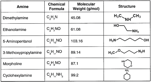
Table 2. Common neutralizing amines
Another question that arises concerns pH monitoring. Measurement of pH is difficult in high-purity waters (generally understood to have conductivity values <2μS·cm–1), and for high-pressure steam generators algorithms have been developed that calculate pH based on specific conductivity and CACE measurements. These are accurate within the typical recommended feedwater pH ranges. But, with lower-purity industrial boiler feedwaters, direct pH measurements are more reliable. Thus, pH is an on-line measurement recommended for sample point #8 or #9, if available.
Iron monitoring of sample points #6, #7, and #8 or #9 is highly recommended to track feedwater corrosion and evaluate the performance of chemical treatment programs. Similarly, regular iron monitoring of condensate return (#4) should be considered, in large measure to ensure that chemical treatment programs are protecting the often very large carbon steel piping networks.
Note: Copper alloys are often a prime material for heat exchanger tubes. Space limitations prevent a discussion of chemical treatment methods for these materials, but periodic grab sample analyses for copper are recommended for systems that have copper alloys to ensure that the treatment program is performing properly.
As the authors have reported previously [7,8], simple colorimetric lab methods have traditionally been used to monitor dissolved iron contamination. The common colorimetric method for dissolved iron is based on the extremely sensitive ferrozine ferrous iron complex described
by Stookey [9]. Ferrozine complexes with dissolved ferrous iron to form an intensely colored purple complex. The dissolved ferrous iron concentration may be determined by measuring the absorbance of this complex. Modifications of this traditional method now allow for the determination of both dissolved iron and particulate iron oxides at very low concentrations.
The reductive dissolution of iron oxides via thiol-containing compounds has been thoroughly investigated by Waite et al. Thioglycolic acid (TGA) has been used to successfully dissolve and reduce various iron oxides. While magnetite is dissolved relatively easily with TGA, hematite has been shown to be much more resistant to this method [10,11]. However, TGA is compatible with the sensitive ferrozine reagent and is commercially available as a combined reagent. This combination digestion-reduction-detection reagent is particularly useful for simplifying analysis and minimizing contamination.
Complete dissolution of particulate magnetite and hematite can be achieved with a 135°C, 30-min closed vessel digestion using 240μL of combination reagent and 12mL of sample. The digestion is carried out in a 20mL glass vial heated in an aluminum block. After the sample has cooled, the absorbance is determined with a spectrophotometer and a 1in. (2.54 cm) cell (see Figure 5). The calibrated range using this procedure is 1–100μg·L–1 with a method detection limit (MDL) of 0.3μg·L–1.
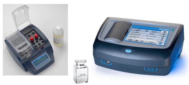
Figure 5. Combination reagent, digestion vials, and heater block (left); 1-inch sample cell (center) and spectrophotometer (right).
On-line methods are available for iron monitoring, including those based on nephelometry, but these are often beyond the budget at industrial plants. IAPWS has generated a TGD which discusses the variety of analytical methods that can be used for iron [12].
Boiler Blowdown (#10)
The choice of analyzers for boiler blowdown can be challenging, because with low-pressure units a variety of treatment programs are possible. In the 1930s, as power generating units increased in number and size, tri-sodium phosphate (Na3PO4, also known as TSP) became a popular boiler pH conditioning chemical for drum boilers.
Na3PO4 + H2O⇔NaH2PO4 + NaOH (6)
In the power industry, phosphate treatment programs have undergone much evolution from TSP to coordinated and congruent programs, with a return to TSP only, albeit in low dosages. For industrial boilers, phosphate treatment methods remain a strong choice, but are not always limited just to TSP. The lower temperatures may allow chemistry along the lines of the old coordinated phosphate programs, with sodium-to-phosphate ratios less than 3:1. A second function of phosphate, which is particularly important for units in which hardness ions may periodically ingress, is to control scale formation. Phosphate and the alkalinity produced by its reaction with water (see Eq. (6)) react with hardness ions to, at least to some extent, form soft sludges as opposed to hard scale.
Often recommended with phosphate treatment are sludge conditioners consisting of water-soluble polymers that help to keep solids in suspension by a combination of dispersion, crystal modification, and sequestration. Iron particulates from condensate return system corrosion can be problematic, where sludge conditioners help to keep the particles in suspension for subsequent blowdown. These polymers can sometimes serve as a stand-alone treatment, particularly if hardness ingress is not an issue. Polymer formulations frequently include an alkalinity builder to maintain pH in a mildly basic pH range similar to phosphate.
Chelant chemistry has at times been successfully employed in industrial drum units, in which the chemicals directly bind with metals to keep them suspended. Ethylenediaminetetraacetic acid (EDTA) is the most widely known chelant. However, improper use of chelants can cause localized corrosion of boiler components.
So, analytical parameters for industrial drum units obviously include pH and phosphate, if that chemical is utilized. As with utility boilers, specific and cation conductivity are important measurements to determine the general concentration of dissolved solids in the boiler and adjust blowdown accordingly. Monitoring of polymer concentrations has been improved with the development of tagged products that respond to fluorescence.
Saturated Steam (#11)
In general, steam purity in low-pressure boilers is not problematic because the risk of carryover, as compared to high-pressure utility units, is lessened due to the lower pressures and temperatures. However, as the case history that introduced the condensate return section outlined, carryover issues cannot be ignored. In that instance, the organic impurities initiated foaming and subsequent carryover, but other issues that can induce carryover include damaged or failed steam separating components in the boiler drum, sudden load swings that cause surging, excessive mineral content in the boiler water, poor drum design, lack of operator attention to water levels, and so on. A common grab sample analysis in the power industry is sodium, as this element can be measured with excellent accuracy. Concentrations in a low μg·L–1 range should be the norm. According to Table 1, total dissolved solids (TDS) is another analytical parameter, although these analyses require time to filter the sample, weigh the resultant liquid and container, and then dry it to completion and re-weigh the container with the dried solids. Saturated steam is the most difficult fluid in a steam generator to sample accurately, as the steam is very close to two-phase conditions that can introduce inaccuracies unless rigorous sampling techniques are employed. This includes the use of an isokinetic sampling device in the steam line. Again, refer to reference [1].
Superheated Steam (#12)
In the power industry, superheated steam, and ideally reheat steam, is the best choice for online analyses. Reheat sampling accounts for all prior effects, including attemperation, that can influence the steam, and is particularly important to protect the intricate and precisely machined turbine(s) downstream. This layout contrasts with industrial boilers, which normally do not have reheaters and often may not drive turbines or have attemperation. Several of these scenarios are examined below.
The steam purity guidelines shown in Table 1 only include one parameter, TDS. This is not an analysis that can be performed on-line. Some continuous on-line analyses are necessary to guard against upsets that could cause problems in downstream equipment. One possibility is CACE, which is a general indication of salt (primarily chlorides and sulfates) carryover in the steam. Sodium is another reliable and relatively inexpensive measurement for monitoring mechanical carryover. For situations like that outlined in the earlier case history, TOC is a potential choice.
The situation becomes more complex if some of the steam also drives turbines. The instrumentation mentioned above would definitely be in order, and for higher-pressure boilers such as might be found at a co-generation plant could include silica. Silica (SiO2) is a vaporous carryover product, where the carryover effects decidedly increase with increasing pressure. Silica precipitates on turbine blades, and while not corrosive can negatively impact the aerodynamic efficiency of the turbine.
Regarding the attemperation line shown in Figure 1, steam attemperation should only be employed if high-purity water (sodium, chloride, and sulfate concentrations of less than 2μg·L–1) is available for the attemperation sprays. Introduction of impurity-laden water directly to steam can quickly cause serious problems. In power units, attemperation water is usually taken from the boiler feed pump discharge, which provides enough pressure to overcome that of the steam. Thus, feedwater analyses also provide data on the purity of the attemperation sprays. If another source is utilized, then the attemperation water should have its own set of continuous analyzers, with sodium and CACE being prime candidates.
References
[1] Technical Guidance Document: Procedures for the Measurement of Carryover of Boiler Water into Steam, 2008. International Association for the Properties of Water and Steam, IAPWS TGD1-08. Available from http://www.iapws.org.
[2] Byrne, W., Reverse Osmosis, A Practical Guide for Industrial Users, 2002. Tall Oaks Publishing, Inc., Littleton, CO, USA, 2nd Edition.
[3] Sturla, P., “Oxidation and Deposition Phenomena in Forced Circulating Boilers and Feedwater Treatment”, presented at the Fifth National Feedwater Conference, 1973 (Prague, Czechoslovak Socialist Republic).
[4] Consensus on Operating Practices for the Control of Feedwater and Boiler Water Chemistry in Modern Industrial Boilers, 1994. The American Society of Mechanical Engineers, New York, NY, USA, CRTD 34.
[5] Monitoring Leaks in Heat Exchangers, 1995. Turner Designs Hydrocarbon Instruments, Fresno, CA, USA.
[6] Dooley, B., Lister, D., “Flow-Accelerated Corrosion in Steam Generating Plants”, PowerPlant Chemistry 2018, 20(4), 194.
[7] Kuruc, K., Johnson, L., “Further Advances in Monitoring Low-Level Iron in the Steam Cycle”, PowerPlant Chemistry 2015, 17(2), 94.
[8] Buecker, B., Kuruc, K., Johnson, L., The Integral Benefits of Iron Monitoring for Steam Generation Chemistry Control, 2019. Available from https://www.power-eng.com.
[9] Stookey, L. L., “Ferrozine – A New Spectrophotometric
Reagent for Iron”, Analytical Chemistry 1970, 42(7), 779.
[10] Waite, T. D., Torikov, A., Smith, J. D., “Photoassisted
Dissolution of Colloidal Iron Oxides by Thiol-Containing Compounds: I.
Dissolution of Hematite (α-Fe2O3)”, Journal of Colloid and Interface Science 1986, 112(2), 412.
[11] Baumgartner, E., Blesa, M. A., Maroto, A. J. G., “Kinetics of the Dissolution of Magnetite in Thioglycolic Acid Solutions”, Journal of
the Chemical Society, Dalton Transactions 1982, 1649.
[12] Technical Guidance Document: Corrosion Product Sampling and Analysis for Fossil and Combined Cycle Plants, 2014. International Association for the Properties of Water and Steam, IAPWS TGD6-13(2014). Available from http://www.iapws.org.
The Authors
Brad Buecker (B.S., Chemistry, Iowa State University, Ames, IA, USA) is a senior technical publicist with ChemTreat. He has many years of experience in or affiliated with the power industry, much of it in steam generation chemistry, water treatment, air quality control, and results engineering positions with City Water, Light & Power (Springfield, IL, USA) and the Kansas City Power & Light Company’s (now Evergy) La Cygne, KS, USA, generating station. Most recently he was a technical specialist with Kiewit Engineering Group Inc. He is a member of the American Chemical Society, American Institute of Chemical Engineers, American Society of Mechanical Engineers, Association of Iron and Steel Technology, National Association of Corrosion Engineers, the Electric Utility Chemistry Workshop planning committee, and the Power-Gen International planning committee. Mr. Buecker has authored many articles and three books on power plant topics.
Ken Kuruc (B.S., Chemistry, John Carroll University, Cleveland, OH, USA) has been active in the power industry for over 25 years. In his current role, Ken provides technical support on all aspects of water quality monitoring for fossil power generation sites across the USA. He has co-authored articles which have appeared in various power industry publications and has presented at numerous utility and water chemistry conferences, including the International Water Conference, where he was awarded the 2019 Paul Cohen Award.
The post Sampling Points and Parameters for Low-Pressure Industrial Steam Generators appeared first on ChemTreat, Inc..
]]>The post Selenium Removal from Industrial Wastewater appeared first on ChemTreat, Inc..
]]>By Dave Karlovich, Vladimir Djukanovic, and Brad Buecker
A critical issue at coal-fired power plants — those remaining and many of those that have shut down — is how to remove selenium from wet scrubber effluent and ash pond wastewater. However, industries such as mining, oil refining, and others face similar difficulties where wastewaters from material extraction or process treatments contain selenium. Heretofore, selenium removal has been capital intensive, as the standard removal methods involved microbiological treatment with large and complex systems. This article outlines fundamental concepts of a new process that can remove selenium via efficient physical-chemical techniques.
Read the rest of the article online today.
The post Selenium Removal from Industrial Wastewater appeared first on ChemTreat, Inc..
]]>The post Dealing with challenging flow measurements appeared first on ChemTreat, Inc..
]]>By Brad Buecker
Past experiences can be examined to show how new technologies help improve flow measurement problems. The following examples are taken from the author’s experience from nearly two decades at two coal-fired power plants and another two years at a chemical plant. This article presents several of these applications ranging from measurement of large flow volumes to obtaining accurate readings in lines with little straight-run piping.
To read more, click here.
The post Dealing with challenging flow measurements appeared first on ChemTreat, Inc..
]]>The post On-Line Chemistry Monitoring: A Critical Necessity for Heat Recovery Steam Generators appeared first on ChemTreat, Inc..
]]>With the decline of coal-fired power generation and the upswing in renewables, a large bridge between the two has been and continues to be simple- and especially combined cycle power generation with natural gas being the primary fuel.
Very common for existing and planned combined cycle power plants is operation with minimal staff. For the gas turbine portion of these plants, “lean and mean” operation may be satisfactory. But often overlooked is that the heat recovery steam generators (HRSGs) require significant attention to prevent corrosion and deposition in these units, which otherwise could impact unit availability and potentially even threaten employee safety in some cases. This article focuses upon the critical on-line water/steam chemistry analyses that are necessary for plant personnel to optimize HRSG performance and reliability.
Sampling Points and Monitoring Parameters
The samples of primary importance throughout the steam-generating network are:
- Makeup treatment system
- Condensate pump discharge
- Feedwater or economizer inlet
- Boiler water
- Saturated steam
- Main and reheat steam
Makeup Treatment System
Even in the tightest steam generators a small amount of process water/steam continually escapes. These losses must be made up with high-purity water. Most common as the core process of makeup systems is reverse osmosis (RO) followed by either mixed-bed ion exchange (MBIX) or electrodeionization (EDI) to “polish” the RO effluent. RO units typically include a number of instruments to monitor system performance, including pressure, temperature, flow, and specific conductivity, which are the subject for a separate discussion. The list below outlines the recommended upper limit for the three recommended sampling parameters of the makeup system effluent.
- Specific conductivity (S.C.): ≤0.1 µS/cm
- Silica: ≤10 parts per billion (ppb)
- Sodium: ≤2 ppb
These measurements ensure that high-purity water is being distributed to the steam generators. A rise in any of the values indicates that either the MBIX resin has reached exhaustion or that a problem has occurred in the EDI unit. Prompt corrective action is necessary.
(Note: In this and the following sections, the normal upper limit, or range, for each parameter is included. This data and many other details may be found in published documents by the Electric Power Research Institute [EPRI]. However, these documents are usually only available to EPRI members. The International Association for the Properties of Water and Steam [IAPWS] offers technical documents that have similar, albeit more condensed, information, which are downloadable from their website, www.iapws.org.)
Condensate Pump Discharge (CPD)
In steam generating power units, the primary location for potential contaminant ingress is the condenser, and particularly water-cooled condensers where a tube leak(s) allows cooling water to infiltrate the high-purity condensate. Cooling water in-leakage will introduce a variety of impurities to the steam generator, which, when subjected to the harsh environment in the boilers (the common term for HRSGs is evaporators) can cause serious problems.
Recommended continuous CPD analyses are:
- Cation Conductivity (CACE): ≤0.2 µS/cm
- S.C.: Consistent with pH
- Sodium: ≤2 ppb
- Dissolved Oxygen: ≤20 ppb
- pH: 9.6 to 10.0 (This is the pH range for the most common HRSG design, the triple-pressure, feed-forward low-pressure type. The range may be a bit different for other HRSG designs.)
Sodium monitoring is very effective for detecting condenser tube leaks. With a tight condenser, sodium levels in the condensate are normally very low (<2 ppb), and in many cases less than 1 ppb. A rise in sodium provides the earliest indication of a condenser tube leak.
Cation conductivity has been re-designated by some research organizations as “conductivity after cation exchange (CACE)” to represent the fact that the sample is routed through a cation exchange column to replace the cations, e.g., ammonium, sodium, calcium, etc. with hydrogen ions. This creates a very dilute acid solution of primarily trace amounts of chloride and sulfate ions, whose conductivity is then measured. As with sodium, a rise in CACE indicates impurity in-leakage. CACE can be influenced by carbon dioxide ingression, often from increased air in-leakage at the condenser. Thus, becoming increasingly popular is degasified CACE, which utilizes either a re-boiler or nitrogen sparging compartment to remove up to 90% or so of the CO2.
Dissolved oxygen analyses are important for monitoring condenser air in-leakage. A sudden increase in dissolved oxygen may indicate a mechanical failure at or near the condenser, which allows excess air to enter the system.
With regard to specific conductivity and pH, ammonia (or sometimes an amine or ammonia/amine blend) is the pH-conditioning agent for condensate/feedwater. However, direct pH measurement of high-purity water can be tricky, and algorithms have been developed to calculate pH based on S.C. and CACE measurements to provide more accurate results. S.C. in high-purity water is directly correlated to the ammonia concentration, and thus S.C. measurements offer better control of ammonia feed than pH.
A parameter not typically monitored continuously, but which can be of some importance is total organic carbon (TOC). For utility steam generators, the recommended TOC limit in the CPD is 100 ppb.
LP Economizer Inlet/Boiler Feed Pump Discharge
The dominant issue with regard to chemistry control in the HRSG feedwater system is minimization of flow-accelerated corrosion, which the authors discussed in a previous Power Engineering article. [1]
The following parameters are recommended for feedwater chemistry:
- CACE: ≤0.2 µS/cm
- S.C: Consistent with pH
- Sodium: ≤2 ppb
- Dissolved Oxygen (range): 5 to 10 ppb (unless the feedwater system contains copper alloys, which are almost never present in HRSG condensate/feedwater systems)
- pH: 9.6 to 10.0 (This is the pH range for the most common HRSG design, the triple-pressure, feed-forward low-pressure type. The range may be a bit different for other HRSG designs.)
- Iron: ≤2 ppb
The discussion for CACE, S.C., pH, and sodium mirrors that for condensate pump discharge. The measurements can provide valuable redundancy in determining whether a potential upset is due to an actual problem or instrument error.
Note the inclusion of iron in this list. Iron monitoring provides a direct measurement of FAC (or hopefully lack thereof) and the corresponding effectiveness of the feedwater chemistry program. Typically, 90 percent or greater of iron corrosion products generated by FAC are particulate in nature. Several methods exist to monitor carbon steel corrosion, and include:
- Continuous particulate monitoring
- Corrosion product sampling
- Grab sample analysis
With respect to the latter, improved grab sampling techniques are available, in which, with proper sample treatment, iron measurements down to 1 ppb are possible. This method can provide near real-time data of corrosion rates, although on a snapshot basis.


Fig. 1. Iron digestion unit/spectrophotometer for grab samples. Photos courtesy of Hach.
A combination of a simple colorimetric total iron laboratory analysis with a sensitive laser nephelometric analyzer can also provide a method for cost effective, quantitative, real-time corrosion monitoring.

Fig. 2. A nephelometer mounted on a water/steam sample panel. Photo courtesy of Hach.
When properly calibrated, the nephelometric measurement units provided by the instrument can be correlated to total iron concentration values. The iron concentration of the feedwater is a direct indicator of steel corrosion. However, any of several species may be present depending upon the feedwater chemistry employed in the process. These include Fe3O4 (magnetite, gray-black color), α-iron (III) oxide (hematite, red color), and a usually minor concentration of dissolved iron. Each of these species produces a different nephelometric response to visible light. Black magnetite absorbs more and reflects less light than red hematite. Dissolved iron does not produce any nephelometric response. In addition, corrosion products range in size from sub-micron to 10 μm in diameter, with an average diameter of 1 μm. [2] This size range poses another challenge for particle monitoring because nephelometers respond differently to different particle sizes.
These variables make it impossible to create a universal nephelometric calibration for quantification of corrosion products. A calibration which is appropriate for a particular sample location with particular corrosion characteristics will not be accurate for a different application with different parameters. Therefore, quantification of total iron via nephelometry must be accomplished through site-specific calibration.
Evaporator (Boiler) Water
Evaporator water sampling is critical for several reasons. First, poor chemistry control and/or poor monitoring can allow unacceptable carryover of excess impurities to the steam. Secondly, most HRSGs are multi-pressure units, where the chemistry in each circuit is different from the other circuits. Comprehensive monitoring is necessary to ensure proper chemistry throughout the steam generator. Thirdly, the highest heat fluxes occur within the evaporators, and particularly the HP evaporator, of HRSGs. The effects of impurity ingress or poor chemistry are magnified by the high temperatures and pressures in these circuits. Consider the classic issue of hydrogen damage, which has plagued high-pressure units for decades.
In this mechanism, the most serious corrosive agent, chloride, that enters during a cooling leak can concentrate under waterwall tube deposits and generate acid. The following equation outlines a common mechanism:
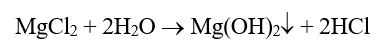
Acid generation is problematic in its own right, but the very small hydrogen atoms will penetrate the steel matrix and then react with carbon in the steel.
Formation of voluminous methane molecules induces cracking, which can then induce failures with very little metal loss.

Fig. 3. Hydrogen damage. Notice the thick-lipped failure, showing little metal loss.
Author Brad Buecker once directly observed the after-effects of severe hydrogen damage on a 1,250 psig conventional steam generator, where the extensive corrosion required complete replacement of the waterwall tubes. [3] Hydrogen damage remains one of the leading corrosion mechanisms in modern steam generators, and is why, as the list below indicates, immediate unit shutdown is required if the boiler water pH drops below 8.0.
Recommended boiler water analyses include:
- pH (<8.0, immediate boiler shutdown)
- CACE
- Specific Conductivity
- Chloride
- Silica
- Phosphate (for those units on phosphate treatment)
- Iron: <5 ppb
The reader will notice no direct limits for most parameters, with the exception of a “drop-dead” lower limit for pH. This is due to the fact that the limits or control ranges are variable based on boiler pressure. EPRI and IAPWS guidelines provide details on how to calculate the proper ranges for any system, where some adjustments may be necessary based upon operating data.
Comment is necessary regarding phosphate. For decades, tri-sodium phosphate (Na3PO4) has been a core boiler water treatment chemical in many drum units. However, control of the phosphate concentration is difficult due to the compound’s reverse solubility, aka “hideout,” above 300°F. Some plant personnel, especially in the power industry, have switched to a caustic (NaOH) feed to eliminate phosphate hideout, but great care is required with these programs to prevent caustic gouging of waterwall tubes. To avoid such issues, inclusion of a condensate polisher in the unit design offers the opportunity to eliminate phosphate or caustic from the boiler water treatment program.
Steam
Steam purity measurements are extremely important, in large part because the turbine is the most finely-machined and expensive piece of equipment in the entire system. Contaminant deposition on turbine blades can lead to corrosion and possible blade failures, which represent a potentially catastrophic situation with the turbine spinning at several thousand rpm. Core monitoring parameters include the following:
- CACE: ≤0.2 µS/cm
- Sodium: ≤2 ppb
- Silica: ≤10 ppb
Sodium provides a direct indication of salt or sodium hydroxide carryover with the steam. Salts will settle in the last rows of the low-pressure turbine, where they can cause pitting and subsequent stress corrosion cracking (SCC) and corrosion fatigue (CF) of turbine blades and rotors. Sodium hydroxide carryover is a very serious issue, as caustic can quickly induce SCC of turbine components.
CACE provides an indirect measurement of chloride and sulfate carryover, and the ≤0.2 µS/cm value has been a long-time guideline for turbine manufacturers. However, the accuracy of CACE is suspect for chloride and sulfate. Now available is reliable instrumentation to monitor trace levels of these two impurities. [4] Current recommended limits for chloride and sulfate are 2 ppb, but in a well-operated unit they can and should be much lower.
It has long been known that silica in steam will precipitate on turbine blades. While the compound is not corrosive, it can influence turbine aerodynamics and reduce efficiency. Thus, the 10-ppb recommended limit above.
Several steam sampling points are available in power generating units. These include saturated, main, and reheat steam samples. Main and reheat steam are the most important, as they provide data on impurities directly entering the turbine, which can also come from contaminated attemperation water. Analysis of saturated steam is less important on a continual basis, but can be valuable periodically to check for mechanical carryover issues from steam drums, with a common cause being damaged or failed moisture separators in the drums. Sodium monitoring is best for this evaluation.
Disclaimer: This discussion represents good engineering practice developed over many years of research and practical experience. However, it is the responsibility of the plant owners to develop reliable monitoring systems based on consultation with industry experts. Many additional details go into the design and subsequent operation of a water/steam chemistry sampling system.
References
- Buecker, B., Kuruc, K., and L. Johnson, “The Integral Benefits of Iron Monitoring for Steam Generation Chemistry Control”; Power Engineering, January 2019.
- Kuruc, K., and L. Johnson, “New Findings on Monitoring Flow-Accelerated Corrosion”; Proceedings of the 35th Annual Electric Utility Chemistry Workshop, June 2-4, 2015, Champaign, Illinois.
- B. Buecker, “Condenser Chemistry and Performance Monitoring: A Critical Necessity for Reliable Steam Plant Operation”; Proceedings of the 60th Annual International Water Conference, October 18-20, 1999, Pittsburgh, Pennsylvania.
- B. Buecker, “An Advancement in Steam Turbine Chemistry Monitoring”; Power Engineering, March 2018.

About the author: Brad Buecker is Senior Technical Publicist with ChemTreat. He has 35 years of experience in or affiliated with the power industry, much of it in steam generation chemistry, water treatment, air quality control, and results engineering positions with City Water, Light & Power (Springfield, Illinois) and Kansas City Power & Light Company’s La Cygne, Kansas station. He also spent two years as acting water/wastewater supervisor at a chemical plant. Buecker has a B.S. in chemistry from Iowa State University with additional course work in fluid mechanics, energy and materials balances and advanced inorganic chemistry. He is a member of the American Chemical Society, American Institute of Chemical Engineers, American Society of Mechanical Engineers, Association of Iron and Steel Technology, Cooling Technology Institute (via corporate membership), National Association of Corrosion Engineers, the Electric Utility Chemistry Workshop planning committee, the EPRI-sponsored Power Plant & Environmental Chemistry Committee, and the Power-Gen International planning committee. Buecker has authored many articles and three books on power plant and water/steam chemistry topics. He may be reached at bradley.buecker@chemtreat.com.

Ken Kuruc is Industry Account Manager for Fossil Power with Hach. He has 25 years of experience in working with the power industry, primarily surrounding the steam cycle. His focus in early years has been with dissolved gases for corrosion monitoring as part of Orbisphere, which has since been integrated into Hach. Kuruc has a B.S. in Chemistry from John Carroll University (University Heights, OH) and has presented on this subject along with others at power conferences across the U.S. He may be reached at kkuruc@hach.com.
This article was originally published in Power Engineering magazine and has been republished with permission. Click here to read it on the Power Engineering website.
To read this article in Spanish, click here.
To read this article in Portuguese, click here.
The post On-Line Chemistry Monitoring: A Critical Necessity for Heat Recovery Steam Generators appeared first on ChemTreat, Inc..
]]>The post Monitoramento químico on-line: uma necessidade básica para geradores de vapor de recuperação de calor appeared first on ChemTreat, Inc..
]]>Com o declínio da geração de energia produzida a carvão e a ascensão de fontes renováveis, uma grande ponte entre os dois tem sido e continua a ser a geração de energia de ciclo simples e especialmente combinado com gás natural como o combustível principal.
Algo muito comum para as usinas existentes e planejadas de energia de ciclo combinado é a operação com uma equipe mínima. Para a parte de turbina a gás dessas usinas, a operação “lean and mean” (simplificada e otimizada) pode ser satisfatória. Porém, um fator muitas vezes negligenciado é que os geradores de vapor de recuperação de calor (Heat Recovery Steam Generators, HRSGs) exigem atenção significativa para prevenir corrosão e deposição nessas unidades, o que, de outra forma, poderia afetar a disponibilidade da unidade e, em alguns casos, até mesmo ameaçar a segurança dos funcionários. Este artigo concentra-se nas análises essenciais de química de água/vapor on-line necessárias para a equipe da usina otimize o desempenho e a confiabilidade do HRSG.
Pontos de amostragem e parâmetros de monitoramento
As amostras de importância primária em toda a rede geradora de vapor são:
- Sistema de tratamento de água de alimentação
- Descarga da bomba de condensado
- Entrada de água de alimentação ou economizador
- Água de caldeira
- Vapor saturado
- Vapor principal e de reaquecimento
Sistema de tratamento de Água de Alimentação
Mesmo nos geradores de vapor mais compactos, uma pequena quantidade de água/vapor de processo escapa continuamente. Essas perdas devem ser compensadas com água de alta pureza. O processo principal de sistemas de alimentação mais comum é a osmose reversa (reverse osmosis, RO) seguida por troca iônica de leito misto (mixed-bed ion exchange, MBIX) ou eletrodeionização (EDI) para “polir” o efluente da RO. As unidades de RO normalmente incluem vários instrumentos para monitorar o desempenho do sistema, incluindo pressão, temperatura, vazão e condutividade específica, que são assuntos para uma discussão à parte. A lista abaixo descreve o limite superior recomendado para os três parâmetros de amostragem recomendados de efluentes do sistema de alimentação.
- Condutividade específica (specific conductivity, S.C.): ≤0,1 µS/cm
- Sílica: ≤10 partes por bilhão (ppb)
- Sódio: ≤2 ppb
Essas medições garantem que a água de alta pureza seja distribuída aos geradores de vapor. Um aumento em qualquer um dos valores indica que a resina de MBIX atingiu a exaustão ou que ocorreu um problema na unidade de EDI. É necessária ação corretiva imediata.
(Observação: nesta e nas próximas seções está incluído o limite ou o intervalo superior normal para cada parâmetro. Esses dados e muitos outros detalhes podem ser encontrados em documentos publicados pelo Electric Power Research Institute [EPRI]. Entretanto, esses documentos normalmente estão disponíveis apenas para integrantes do EPRI. A The International Association for the Properties of Water and Steam [IAPWS] oferece documentos técnicos com informações semelhantes, embora mais resumidas, que podem ser baixadas do seu site, www.iapws.org)
Descarga da bomba de condensado (Condensate Pump Discharge, CPD)
Em unidades de energia geradoras de vapor, o principal local para a possível entrada de contaminantes é o condensador, e especialmente condensadores resfriados a água onde um vazamento no tubo permite que a água de resfriamento infiltre o condensado de alta pureza. O vazamento da água de resfriamento introduzirá uma série de impurezas no gerador de vapor, que, ao ser submetido ao ambiente agressivo nas caldeiras, (o termo comum para HRSGs é evaporadores), pode causar sérios problemas.
As análises contínuas recomendadas de CPD são:
- Condutividade de catiônica (CACE): ≤0,2 µS/cm
- S.C.: consistente com pH
- Sódio: ≤2 ppb
- Oxigênio dissolvido: ≤20 ppb
- pH: 9,6 a 10,0 (Essa é a faixa de pH para o projeto mais comum de HRSG, a um tipo de pressão tripla e de alimentação direta. O intervalo pode ser um pouco diferente para outros projetos de HRSG.)
O monitoramento de sódio é muito eficaz para detectar vazamentos no tubo do condensador. Com um condensador compacto, os níveis de sódio no condensado são normalmente muito baixos (<2 ppb) e, em muitos casos, abaixo de 1 ppb. Um aumento no sódio fornece uma indicação precoce de vazamento no tubo do condensador.
A condutividade catiônica foi redesignada por algumas organizações de pesquisa como “condutividade após troca de cátions (conductivity after cation exhange, CACE)” para representar o fato de que a amostra é direcionada através de uma coluna de troca catiônica para substituir os cátions, por exemplo, amônio, sódio, cálcio etc. por íons de hidrogênio. Isso cria uma solução de ácido muito diluída, basicamente de quantidades vestigiais de íons de cloreto e de sulfato, cuja condutividade é, então, medida. Como ocorre com o sódio, um aumento na CACE indica vazamento de impurezas. A CACE pode ser influenciada pela entrada de dióxido de carbono, muitas vezes proveniente de um aumento no vazamento de ar no condensador. Sendo assim, o que tem se tornado cada vez mais popular é a CACE desgaseificada, que utiliza um refervedor ou um compartimento de aspersão de nitrogênio para remover aproximadamente 90% do CO2.
As análises de oxigênio dissolvido são importantes para monitorar o vazamento de ar do condensador. Um aumento repentino no oxigênio dissolvido pode indicar uma falha mecânica no condensador ou próxima a ele, o que permite que o ar em excesso entre no sistema.
Com relação à condutividade e ao pH específicos, a amônia (ou, às vezes, uma amina ou uma mistura de amônia/amina) é o agente condicionador de pH para o condensado/a água de alimentação. No entanto, a medição direta de pH da água de alta pureza pode ser complicada e algoritmos foram desenvolvidos para calcular o pH com base nas medições de S.C. e de CACE para obtenção de resultados mais precisos. A S.C. em água de alta pureza está diretamente correlacionada à concentração de amônia e, portanto, as medições de S.C. oferecem melhor controle da alimentação de amônia do que de pH.
Um parâmetro que, em geral, não é monitorado continuamente, mas que pode ter alguma importância é o carbono orgânico total (total organic carbon, TOC). Para geradores de vapor em utilidades, o limite de TOC recomendado na CPD é de 100 ppb.
Descarga da bomba de alimentação da caldeira/entrada do economizador LP
O principal problema no que diz respeito ao controle químico no sistema de água de alimentação HRSG é a minimização da corrosão acelerada pela vazão, o que os autores discutiram em um artigo anterior sobre Engenharia de energia. [1]
Os parâmetros a seguir são recomendados para a química de água de alimentação:
- CACE: ≤0,2 µS/cm
- S.C: consistente com pH
- Sódio: ≤2 ppb
- Oxigênio dissolvido (intervalo): 5 a 10 ppb (a menos que o sistema de água de alimentação contenha ligas de cobre, que quase nunca estão presentes nos sistemas de condensado/água de alimentação de HRSG)
- pH: 9,6 a 10,0 (Essa é a faixa de pH para o projeto mais comum de HRSG, a um tipo de pressão tripla e de alimentação direta. O intervalo pode ser um pouco diferente para outros projetos de HRSG.)
- Ferro: ≤2 ppb
A discussão sobre CACE, S.C., pH e sódio é a mesma sobre a descarga da bomba de condensado. As medições podem oferecer redundância valiosa para determinar se uma possível anomalia é decorrente de um problema real ou erro de instrumento.
Observe a inclusão de ferro nessa lista. O monitoramento de ferro fornece uma medição direta de FAC (ou, espera-se, a falta dela) e a eficácia correspondente do programa químico de água de alimentação. Normalmente, 90% ou mais dos produtos de corrosão de ferro gerados por FAC são de natureza particulada. Existem vários métodos para monitorar a corrosão do aço carbono, os quais incluem:
- Monitoramento contínuo de partículas
- Amostragem de produtos de corrosão
- Análise de amostra de coleta
No que diz respeito ao último, estão disponíveis técnicas aprimoradas de amostragem de coleta, em que, com o tratamento de amostra adequado, são possíveis medições de ferro até 1 ppb. Esse método pode fornecer dados praticamente em tempo real das taxas de corrosão, embora a base seja limitada.


Fig. 1. Unidade de digestão de ferro/espectrofotômetro para amostras de coleta. Fotos cedidas pela Hach.
Uma combinação de uma análise de laboratório de ferro total colorimétrico simples com um laser sensível, o analisador nefelométrico também pode fornecer um método para monitoramento de corrosão econômico, quantitativo e em tempo real.
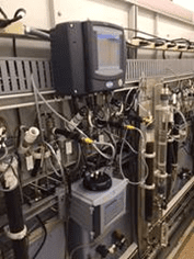
Fig. 2. Um nefelômetro instalado em um painel de amostra de água/vapor. Foto cedida pela Hach.
Quando devidamente calibradas, as unidades de medição nefelométrica fornecidas pelo instrumento podem ser correlacionadas aos valores totais de concentração de ferro. A concentração de ferro da água de alimentação é um indicador direto de corrosão do aço. No entanto, qualquer uma das várias espécies pode estar presente dependendo da química de água de alimentação utilizada no processo. Elas incluem Fe3O4 (magnetita, cor cinza-preta), óxido de α-Fe (III) (hematita, cor vermelha) e uma concentração geralmente menor de ferro dissolvido. Cada uma dessas espécies produz uma resposta nefelométrica diferente à luz visível. A magnetita preta absorve mais e reflete menos luz do que a hematita vermelha. O ferro dissolvido não produz nenhuma resposta nefelométrica. Além disso, os produtos de corrosão variam em tamanho de submicron a 10 μm de diâmetro, com um diâmetro médio de 1 μm. [2] Essa faixa de tamanho representa outro desafio para o monitoramento de partículas porque os nefelômetros respondem de forma diferente a diferentes tamanhos de partículas.
Essas variáveis tornam impossível criar uma calibração nefelométrica universal para a quantificação de produtos de corrosão. Uma calibração adequada para um local de amostra específico com características de corrosão próprias não será precisa para uma aplicação diferente com parâmetros diferentes. Portanto, a quantificação do ferro total por nefelometria deve ser realizada através da calibração específica do local.
Água do evaporador (caldeira)
A amostragem de água do evaporador é fundamental por vários motivos. Primeiro, o controle químico e/ou o monitoramento deficitários podem permitir a transferência inaceitável de impurezas excessivas ao vapor. Em segundo lugar, a maioria dos HRSGs são unidades de várias pressões, onde a química em cada circuito é diferente dos demais circuitos. O monitoramento abrangente é necessário para garantir a química adequada em todo o gerador de vapor. Em terceiro lugar, os maiores fluxos de calor ocorrem dentro dos evaporadores e, especialmente, do evaporador HP, dos HRSGs. Os efeitos da entrada de impurezas ou da química deficitária são ampliados pelas altas temperaturas e pressões nesses circuitos. Considere o problema clássico de danos por hidrogênio, que tem prejudicado unidades de alta pressão há décadas.
Nesse mecanismo, o agente corrosivo de maior gravidade, o cloreto, que entra durante um vazamento de resfriamento, pode se concentrar em depósitos de tubos de parede d’água e gerar ácido. A seguinte equação descreve um mecanismo comum:
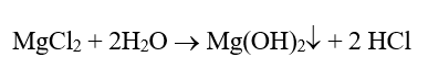
A geração de ácidos é problemática por si só, mas os átomos de hidrogênio muito pequenos penetrarão a matriz de aço e, em seguida, reagirão com o carbono no aço.
A formação de moléculas de metano volumosas induz rachaduras, o que pode, então, provocar falhas com pouquíssima perda de metal.
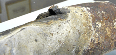
Fig. 3. Danos causados por hidrogênio. Observe a falha de corte “thick-lipped failure”, mostrando pouca perda de metal.
O autor Brad Buecker observou diretamente os seguintes efeitos de danos graves causados por hidrogênio em um gerador de vapor convencional de 1.250 psig em que a corrosão extensa exigiu substituição completa dos tubos de parede d’água. [3] O dano ao hidrogênio continua sendo um dos principais mecanismos de corrosão nos geradores de vapor modernos e é por isso que, como a lista abaixo indica, é necessário desligar imediatamente a unidade se o pH da água da caldeira cair abaixo de 8,0.
As análises recomendadas de água da caldeira incluem:
- pH (<8,0, desligamento imediato da caldeira)
- CACE
- Condutividade específica
- Cloreto
- Sílica
- Fosfato (para essas unidades no tratamento de fosfato)
- Ferro: <5 ppb
O leitor não perceberá limites diretos para a maioria dos parâmetros, com exceção de um limite inferior considerável de pH. Isso se deve ao fato de que os limites ou as faixas de controle são variáveis com base na pressão da caldeira. As diretrizes EPRI e IAPWS fornecem detalhes sobre como calcular as faixas adequadas para qualquer sistema, onde alguns ajustes podem ser necessários com base nos dados operacionais.
É necessário comentar sobre o fosfato. Por décadas, o fosfato trissódico (Na3PO4) tem sido um produto químico de tratamento de água de caldeira central em muitas unidades. No entanto, o controle da concentração de fosfato é difícil devido à solubilidade reversa do composto, também conhecida como “hide out”, acima de 300o F. Alguns profissionais, especialmente no setor de energia, mudaram para uma alimentação cáustica (NaOH) para eliminar o “hide out” de fosfato, mas é necessário um grande cuidado com esses programas para evitar a “caustic gouging” de tubos de parede d’água. Para evitar esses problemas, a inclusão de um polidor de condensado no desenho da unidade oferece a oportunidade de eliminar fosfato ou substância corrosiva a partir do programa de tratamento de água da caldeira.
Vapor
As medições de pureza do vapor são extremamente importantes, em grande parte porque a turbina é o equipamento mais refinado e caro de todo o sistema. A deposição de contaminantes nas pás da turbina pode levar à corrosão e a possíveis falhas na lâmina, o que representa uma situação possivelmente catastrófica, pois a turbina gira a vários milhares de rpm. Os parâmetros de monitoramento essenciais incluem os seguintes:
- CACE: ≤0,2 µS/cm
- Sódio: ≤2 ppb
- Sílica: ≤10 ppb
O sódio fornece uma indicação direta do sal ou da transferência de hidróxido de sódio com o vapor. Os sais se concentrarão nas últimas linhas da turbina de baixa pressão, onde podem causar corrosão e subsequente rachadura por corrosão por tensão (stress corrosion cracking, SCC) e fadiga por corrosão (corrosion fatigue, CF) nas pás e nos rotores da turbina. A transferência de hidróxido de sódio é um problema muito sério, pois a substância corrosiva pode provocar rapidamente a SCC dos componentes da turbina.
A CACE fornece uma medição indireta da transferência de cloreto e de sulfato, e o valor de ≤0,2 µS/cm tem sido uma diretriz de longo prazo para os fabricantes de turbinas. No entanto, a precisão da CACE é questionável para cloreto e sulfato. Atualmente, existe instrumentação confiável para monitorar os níveis de traços dessas duas impurezas. [4] Os limites atuais recomendados para cloreto e sulfato são de 2 ppb, mas em uma unidade bem operada eles podem e precisam ser muito menores.
Há muito tempo, sabe-se que a sílica no vapor causa formação de precipitado sobre as pás da turbina. Embora o composto não seja corrosivo, ele pode influenciar a aerodinâmica da turbina e reduzir a eficiência. Por isso, foi recomendado anteriormente o limite de 10 ppb.
Vários pontos de amostragem de vapor estão disponíveis em unidades de geração de energia. Eles incluem amostras de vapor saturadas, principais e de reaquecimento. O vapor principal e o de reaquecimento são os mais importantes, pois oferecem dados sobre impurezas que entram diretamente na turbina, o que também podem vir da água atemperada contaminada. A análise do vapor saturado é menos importante, mas pode ser valiosa periodicamente para verificar problemas de transferência mecânica de tambores de vapor, em que uma causa comum são danos ou falhas em separadores de umidade nos tambores. O monitoramento de sódio é melhor para esta avaliação.
Isenção de responsabilidade: esta discussão representa uma prática de engenharia recomendada desenvolvida ao longo de muitos anos de pesquisa e de experiência prática. No entanto, é responsabilidade dos encarregados pela usina desenvolverem sistemas de monitoramento confiáveis baseados na consulta de especialistas do setor. Muitos detalhes adicionais fazem parte do projeto e da subsequente operação de um sistema de amostragem química de água/vapor.
Referências
- Buecker, B., Kuruc, K. e L. Johnson, “The Integral Benefits of Iron Monitoring for Steam Generation Chemistry Control” Power Engineering, janeiro de 2019.
- Kuruc, K. e L. Johnson, “New Findings on Monitoring Flow-Accelerated Corrosion”; relatório do 35th Annual Electric Utility Chemistry Workshop, de 2 a 4 de junho de 2015, Champaign, Illinois.
- B. Buecker, “Condenser Chemistry and Performance Monitoring: A Critical Necessity for Reliable Steam Plant Operation; relatório da 60th Annual International Water Conference, 18 a 20 de outubro de 1999, Pittsburgh, Pensilvânia.
- B. Buecker, “An Advancement in Steam Turbine Chemistry Monitoring”; Power Engineering, março de 2018.

Sobre o autor: Brad Buecker é redator técnico sênior da ChemTreat. Ele tem 35 anos de experiência direta ou indiretamente ligada ao setor de energia, grande parte dela em cargos relacionados à química de geração de vapor, ao tratamento de água, ao controle de qualidade de ar e à engenharia de resultados na City Water, Light & Power (Springfield, Illinois) e na estação de La Cygne, Kansas, da City Power & Light Company. Ele também atuou por dois anos como supervisor encarregado de água/água residual em uma usina química. Buecker tem bacharelado em química pela Iowa State University, com curso complementar em mecânica de fluidos, energia e equilíbrio de materiais, e química inorgânica avançada. É membro da American Chemical Society, do American Institute of Chemical Engineers, da American Society of Mechanical Engineers, da Association of Iron and Steel Technology, do Cooling Technology Institute (por meio de associação corporativa), da National Association of Corrosion Engineers, do comitê de planejamento do Electric Utility Chemistry Workshop, do Power Plant & Environmental Chemistry Committee patrocinado pelo EPRI e do comitê de planejamento da Power-Gen International. Buecker é autor de muitos artigos e de três livros sobre temas de usina de energia e de química de água/vapor. Seu e-mail para contato é bradley.buecker@chemtreat.com.

Ken Kuruc é gerente de contas industrial de energia fóssil da Hach. Ele tem 25 anos de experiência profissional na indústria de energia, principalmente em ciclo de vapor. Seu foco nos primeiros anos foi em gases dissolvidos para monitoramento de corrosão como parte da Orbisphere, que desde então foi integrada à Hach. Kuruc tem bacharelado em ciências químicas pela John Carroll University (University Heights, OH) e já foi palestrante sobre esse assunto, além de outros, em conferências de energia nos EUA. Seu e-mail para contato é kkuruc@hach.com.
Este artigo foi originalmente publicado na Revista Power Engineering. A versão original em inglês pode ser encontrada no website da Power Engineering: https://www.power-eng.com/2020/05/01/on-line-chemistry-monitoring-a-critical-necessity-for-heat-recovery-steam-generators/
Para ler este artigo em espanhol, clique aqui.
The post Monitoramento químico on-line: uma necessidade básica para geradores de vapor de recuperação de calor appeared first on ChemTreat, Inc..
]]>The post Monitoreo químico en línea: una necesidad crítica para los generadores de vapor de recuperación de calor appeared first on ChemTreat, Inc..
]]>Con la disminución de la generación de energía a carbón y el alza en las energías renovables, un punto medio entre ambas ha sido y continúa siendo una generación de energía de ciclo simple y, en especial, combinado, con el gas natural siendo el combustible primario.
Algo muy común para las plantas de energía de ciclo combinado existentes y planificadas, es la operación con el mínimo de personal. Para la porción de turbinas de gas de estas plantas, la operación “delgada y directa” puede ser satisfactoria. Pero, a menudo, se ignora que los generadores de vapor de recuperación de calor (heat recovery steam generators, HRSG) requieren una atención significativa para prevenir la corrosión y la deposición en estas unidades, lo que podría afectar la disponibilidad de la unidad e incluso amenazar la seguridad de los empleados en algunos casos. Este artículo se centra en los análisis críticos de química de agua/vapor en línea que son necesarios para que el personal de planta optimice el rendimiento y la confiabilidad de los HRSG.
Puntos de muestreo y parámetros de monitoreo
Las muestras de importancia principal en toda la red generadora de vapor son:
- Sistema de tratamiento de aporte
- Descarga de la bomba de condensado
- Agua de alimentación o entrada al economizador
- Agua de caldera
- Vapor saturado
- Vapor principal y recalentado
Sistema de tratamiento de aporte
Incluso en los generadores de vapor más herméticos, una pequeña cantidad de agua/vapor de proceso se escapa continuamente. Estas pérdidas deben reponerse con agua de alta pureza. Esto es lo más común, ya que el proceso central de los sistemas de aporte es la ósmosis inversa (reverse osmosis, RO) seguida por intercambio iónico de lecho mixto (mixed-bed ion exchange, MBIX) o electrodesionización (EDI) para “pulir” el efluente de RO. Por lo general, las unidades de RO incluyen una serie de instrumentos para monitorear el rendimiento del sistema, incluyendo presión, temperatura, flujo y conductividad específica, que son objeto de un análisis por separado. La siguiente lista describe el límite superior recomendado para los tres parámetros de muestreo recomendados del efluente del sistema de aporte.
- Conductividad específica (specific conductivity, S.C.): ≤0,1 µS/cm
- Sílice: ≤10 partes por mil millones (parts per billion, ppb)
- Sodio: ≤2 ppb
Estas mediciones garantizan que se distribuya agua de alta pureza a los generadores de vapor. Un aumento en cualquiera de los valores indica que la resina de MBIX ha alcanzado el agotamiento o que ha ocurrido un problema en la unidad de EDI. Es necesario tomar medidas correctivas inmediatas.
(Nota: en esta y en las siguientes secciones, se incluye el límite superior normal o el rango para cada parámetro. Estos datos y muchos otros detalles pueden encontrarse en documentos publicados por el Instituto de Investigación de Energía Eléctrica [Electric Power Research Institute, EPRI]. Sin embargo, estos documentos generalmente están disponibles solo para los miembros del EPRI. La Asociación Internacional para las Propiedades de Agua y Vapor [International Association for the Properties of Water and Steam, IAPWS] ofrece documentos técnicos que tienen información similar, aunque más resumida, que se puede descargar desde su sitio web, www.iapws.org.)
Descarga de la bomba de condensado (CPD)
En las unidades de potencia generadoras de vapor, la ubicación principal para el ingreso potencial de contaminantes es el condensador, y particularmente los condensadores enfriados por agua en los que una fuga en los tubos permite que el agua de enfriamiento se infiltre en el condensado de alta pureza. La infiltración de agua de enfriamiento introducirá una variedad de impurezas al generador de vapor, las cuales, cuando se someten al entorno riguroso en las calderas (el término común para los HRSG es evaporadores) puede causar problemas graves.
Los análisis continuos de descarga de la bomba de condensado (Condensate Pump Discharge, CPD) recomendados son:
- Conductividad catiónica (conductivity after cation exchange, CACE): ≤0,2 µS/cm
- S.C.: consistente con el pH
- Sodio: ≤2 ppb
- Oxígeno disuelto: ≤20 ppb
- pH: 9,6 a 10,0 (este es el rango de pH para el diseño de HRSG más común, de triple presión, de tipo de presión baja con alimentación hacia adelante. El rango puede ser un poco distinto para otros diseños de HRSG).
El análisis de CACE, S.C., pH y sodio refleja los parámetros para la descarga de la bomba de condensado. Las mediciones pueden proporcionar una redundancia valiosa para determinar si una posible inestabilidad se debe a un problema real o un error de instrumento.
Observe la inclusión de hierro en esta lista. El monitoreo del hierro proporciona una medición directa de FAC (o, con suerte, de la falta de esta) y la efectividad correspondiente del programa químico del agua de alimentación. Generalmente, el 90 % o más de los productos de corrosión del hierro generados por FAC son de naturaleza particulada. Existen varios métodos para monitorear la corrosión del acero al carbono, incluyendo los siguientes:
- Monitoreo continuo de partículas
- Muestreo de productos de corrosión
- Análisis de muestras
Con respecto al último método, se dispone de técnicas mejoradas de obtención de muestras en las cuales, con el tratamiento de muestra adecuado, es posible realizar mediciones de hierro de hasta 1 ppb. Este método puede proporcionar datos casi en tiempo real de las tasas de corrosión, aunque en forma de fotografía instantánea.

Fig. 1. Unidad de digestión de hierro/espectrofotómetro para muestras. Fotografías cortesía de Hach.
Una combinación de un análisis colorimétrico simple de laboratorio de hierro total con un láser sensible con un analizador nefelométrico también puede proporcionar un método para el monitoreo rentable, cuantitativo y en tiempo real de la corrosión.

Fig. 2. Un nefelómetro montado en un panel de muestra de agua/vapor. Fotografía cortesía de Hach.
Cuando se calibra adecuadamente, las unidades de medición nefelométricas proporcionadas por el instrumento pueden correlacionarse con los valores totales de concentración de hierro. La concentración de hierro del agua de alimentación es un indicador directo de la corrosión del acero. Sin embargo, cualquiera de varias especies químicas podría estar presente dependiendo de la química del agua de alimentación empleada en el proceso. Estas incluyen Fe3O4 (magnetita, color gris-negro), óxido de hierro α (III) (hematita, color rojo) y una concentración generalmente menor de hierro disuelto. Cada una de estas especies químicas produce una respuesta nefelométrica distinta a la luz visible. La magnetita negra absorbe más y refleja menos luz que la hematita roja. El hierro disuelto no produce ninguna respuesta nefelométrica. Además, los productos de corrosión varían en tamaño desde submicras hasta 10 μm de diámetro, con un diámetro promedio de 1 μm. [2] Este rango de tamaño presenta otro desafío para el monitoreo de partículas dado que los nefelómetros responden de manera distinta a distintos tamaños de partículas.
Estas variables hacen imposible crear una calibración nefelométrica universal para la cuantificación de productos de corrosión. Una calibración adecuada para una ubicación de muestra en particular con características de corrosión particulares no será precisa para una aplicación distinta con parámetros distintos. Por lo tanto, la cuantificación del hierro total mediante nefelometría se debe lograr mediante una calibración específica al sitio.
Agua del evaporador (caldera)
El muestreo de agua del evaporador es crítico por varios motivos. En primer lugar, un control deficiente de la química y/o un monitoreo deficiente pueden permitir un arrastre inaceptable del exceso de impurezas al vapor. En segundo lugar, la mayoría de los HRSG son unidades de presión múltiple, donde la química en cada circuito es distinta de los otros circuitos. Es necesario un monitoreo integral para garantizar la química adecuada en todo el generador de vapor. En tercer lugar, los flujos de calor más altos ocurren dentro de los evaporadores, y particularmente el evaporador de alta presión, de los HRSG. Los efectos del ingreso de impurezas o de la mala química se ven magnificados por las altas temperaturas y presiones en estos circuitos. Considere el problema clásico del daño por hidrógeno, que ha afectado las unidades de alta presión durante décadas.
En este mecanismo, el agente corrosivo más grave, el cloruro, que entra durante una fuga de enfriamiento puede concentrarse bajo depósitos en los tubos de pared de agua y generar ácido. La siguiente ecuación describe un mecanismo común:
La generación de ácido es problemática por sí sola, pero los átomos de hidrógeno muy pequeños penetrarán la matriz de acero y luego reaccionarán con el carbono en el acero.
La formación de moléculas de metano voluminosas induce agrietamientos, lo que puede llegar a inducir fallas con muy poca pérdida de metal.

Fig. 3. Daño por hidrógeno. Observe la falla de labio grueso, mostrando poca pérdida de metal.
El autor Brad Buecker observó una vez los efectos posteriores del daño grave por hidrógeno en un generador de vapor convencional de 1250 psig, donde la extensa corrosión requirió un reemplazo completo de los tubos de la pared de agua. [3] El daño por hidrógeno sigue siendo uno de los mecanismos de corrosión principales en los generadores de vapor modernos por lo que, como indica la siguiente lista, se requiere el apagado inmediato de la unidad si el pH del agua de la caldera cae por debajo de 8,0.
Los análisis recomendados de agua de caldera incluyen:
- pH (<8,0, apagado inmediato de la caldera)
- CACE
- Conductividad específica
- Cloruro
- Sílice
- Fosfato (para aquellas unidades en tratamiento con fosfato)
- Hierro: <5 ppb
El lector notará que no hay límites directos para la mayoría de los parámetros, con la excepción de un límite inferior de pH “de caída libre” para el pH. Esto se debe al hecho de que los límites o rangos de control son variables en función de la presión de la caldera. Las guías del EPRI y la IAPWS proporcionan detalles sobre cómo calcular los rangos adecuados para cualquier sistema, en los que pueden ser necesarios algunos ajustes en función de los datos operativos.
Es necesario hacer un comentario con respecto al fosfato. Durante décadas, el fosfato trisódico (Na3PO4) ha sido un producto químico central de tratamiento de agua de calderas en muchas unidades de domos. Sin embargo, el control de la concentración de fosfato es difícil debido a la solubilidad inversa del compuesto, también conocida como “desaparición”, por encima de 149 °C. Algunos miembros del personal de la planta, especialmente en la industria de la energía, han cambiado a una alimentación cáustica (NaOH) para eliminar la desaparición del fosfato, pero es necesario tener mucho cuidado con estos programas para prevenir la formación de ranuras cáusticas en los tubos de la pared de agua. Para evitar tales problemas, la inclusión de un pulidor de condensado en el diseño de la unidad ofrece la oportunidad de eliminar fosfato o material cáustico del programa de tratamiento de agua de calderas.
Vapor
Las mediciones de la pureza del vapor son extremadamente importantes, en gran parte porque la turbina es la pieza de equipo más finamente mecanizada y costosa en todo el sistema. La deposición de contaminantes en los álabes de la turbina pueden provocar corrosión y posibles fallas en los álabes, lo que representa una situación potencialmente catastrófica con la turbina girando a varias miles de rpm. Los parámetros de monitoreo central incluyen los siguientes:
- CACE: ≤0,2 µS/cm
- Sodio: ≤2 ppb
- Sílice: ≤10 ppb
El sodio proporciona una indicación directa de sal o remanente de hidróxido de sodio con el vapor. Las sales se asentarán en las últimas filas de la turbina de baja presión, donde pueden causar picaduras y subsecuentes agrietamientos por corrosión por estrés (stress corrosion cracking, SCC) y fatiga por corrosión (corrosion fatigue, CF) de los álabes y rotores de la turbina. El arrastre de hidróxido de sodio es un problema muy grave, ya que el material cáustico puede inducir rápidamente el SCC de los componentes de la turbina.
La CACE proporciona una medición indirecta del arrastre de cloruro y sulfato, y el valor de ≤0,2 µS/cm ha sido una pauta desde hace mucho tiempo para los fabricantes de turbinas. Sin embargo, se sospecha de la exactitud de la CACE para cloruro y sulfato. Ahora está disponible la instrumentación confiable para monitorear los niveles de traza de estas dos impurezas. [4] Los límites actuales recomendados para cloruro y sulfato son 2 ppb, pero en una unidad bien operada pueden y deben ser mucho más bajos.
Desde hace mucho tiempo se sabe que la sílice en vapor se precipitará en los álabes de la turbina. Si bien el compuesto no es corrosivo, puede influir en la aerodinámica de la turbina y reducir su eficiencia. De ahí el límite anterior recomendado de 10 ppb.
Hay varios puntos de muestreo de vapor disponibles en las unidades generadoras de energía. Estos incluyen muestras vapor saturado, principal y recalentado. El vapor principal y el vapor recalentado son los más importantes, ya que proporcionan datos sobre las impurezas que ingresan directamente a la turbina, lo que también puede provenir del agua contaminada de atemperación. El análisis del vapor saturado es menos importante en forma continua, pero puede ser valioso periódicamente para verificar si hay problemas mecánicos de arrastre de los domos de vapor, siendo una causa común el daño o fallo de los separadores de humedad en los tambores. El monitoreo de sodio es mejor para esta evaluación.
Exención de responsabilidad: Esta discusión representa una buena práctica de ingeniería desarrollada durante muchos años de investigación y experiencia práctica. Sin embargo, es responsabilidad de los propietarios de planta desarrollar sistemas de monitoreo confiables basados en la consulta con expertos de la industria. Muchos detalles adicionales se incluyen en el diseño y la posterior operación de un sistema de muestreo químico de agua/vapor.
Referencias
- Buecker, B., Kuruc, K., y L. Johnson, “The Integral Benefits of Iron Monitoring for Steam Generation Chemistry Control”; Power Engineering, enero de 2019.
- Kuruc, K., y L. Johnson, “New Findings on Monitoring Flow-Accelerated Corrosion”; Proceedings of the 35th Annual Electric Utility Chemistry Workshop, 2 al 4 de junio de 2015, Champaign, Illinois.
- B. Buecker, “Condenser Chemistry and Performance Monitoring: A Critical Necessity for Reliable Steam Plant Operation”; Proceedings of the 60th Annual International Water Conference, 18 al 20 de octubre de 1999, Pittsburgh, Pennsylvania.
- B. Buecker, “An Advancement in Steam Turbine Chemistry Monitoring”; Power Engineering, marzo de 2018.
Acerca del autor: Brad Buecker es publicista técnico sénior en ChemTreat. Tiene 35 años de experiencia en la industria energética o afiliado a esta, gran parte de ellos en posiciones de química de generación de vapor, tratamiento de agua, control de calidad del aire e ingeniería de resultados con City Water, Light & Power (Springfield, Illinois) y la estación La Cygne, Kansas, de Kansas City Power & Light Company. También pasó dos años como supervisor de agua/aguas residuales en una planta química. Buecker tiene una licenciatura en química de la Universidad Estatal de Iowa con trabajos adicionales en mecánica de fluidos, balances de energía y materiales y química inorgánica avanzada. Es miembro de la Sociedad Estadounidense de Química (American Chemical Society), Instituto Americano de Ingenieros Químicos (American Institute of Chemical Engineers), Sociedad Americana de Ingenieros Mecánicos (American Society of Mechanical Engineers), Asociación de Tecnología del Hierro y del Acero (Association of Iron and Steel Technology), Instituto de Tecnología de Enfriamiento (Cooling Technology Institute) (a través de la membresía corporativa), Asociación Nacional de Ingenieros de Corrosión (National Association of Corrosion Engineers), el Comité de Planificación del Taller de Química de plantas eléctricas, el Comité de Química Ambiental y Plantas de Energía patrocinado por EPRI y el Comité de Planificación de Power-Gen International. Buecker ha redactado muchos artículos y tres libros sobre plantas de energía y temas de química de agua/vapor. Puede comunicarse con él al correo bradley.buecker@chemtreat.com.
Ken Kuruc es gerente de cuentas de la industria para Fossil Power en Hach. Tiene 25 años de experiencia en el trabajo con la industria energética, principalmente en torno al ciclo de vapor. Su enfoque en los primeros años ha sido con gases disueltos para el monitoreo de la corrosión como parte de Orbisphere, que desde entonces se ha integrado a Hach. Kuruc tiene una licenciatura en química de la Universidad John Carroll (University Heights, OH) y ha presentado este tema junto con otras personas en conferencias de energía en los EE. UU. Puede comunicarse con él al correo kkuruc@hach.com.
Este artículo fue publicado originalmente en la revista Power Engineering. La versión original en Inglés puede encontrarse en el sitio web de Power Engineering: https://www.power-eng.com/2020/05/01/on-line-chemistry-monitoring-a-critical-necessity-for-heat-recovery-steam-generators/
Para leer este artículo en portugués, haga clic aquí.
The post Monitoreo químico en línea: una necesidad crítica para los generadores de vapor de recuperación de calor appeared first on ChemTreat, Inc..
]]>The post Advances in Cooling Water Treatment for the Steel Industry appeared first on ChemTreat, Inc..
]]>This paper examines advancements in open recirculating water treatment, including a movement from phosphate/phosphonate treatment to all-polymer scale and corrosion control chemistry; selection of oxidizing and non-oxidizing biocides to minimize microbiological fouling; and enhanced analytical instrumentation for precise cooling water chemistry control.
Cooling water is a critical commodity in the steel industry due to the very high heat generation and energy transfer in blast furnaces, basic oxygen and electric arc furnaces, steel finishing processes, etc. Many heat exchangers rely on cooling either directly or indirectly from open recirculating systems, i.e., cooling tower–based networks. Scaling, microbiological fouling and corrosion in these cooling systems can cause serious problems and may even influence plant production. This paper examines advancements and cutting-edge developments in open recirculating cooling water treatment, particularly related to corrosion and scale prevention. The paper also examines improved technology for treating water recovered from direct spray processes. The technology can offer significant cost savings at a plant.
The Scale/Corrosion/Biofouling Triangle
Impurities and microorganisms in water (and in the air that enters cooling towers) influence scale formation, corrosion and fouling via a variety of mechanisms. These problematic issues are often interrelated, as illustrated in Fig. 1.
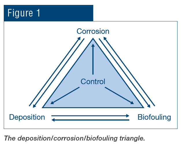
For example, scale formation and biofouling, besides restricting heat transfer, can induce underdeposit and crevice corrosion. Corrosion, in turn, can generate products that may deposit elsewhere and so on.
Scale/Corrosion Inhibitor Evolution
As Fig. 1 indicated, corrosion, fouling and scale formation may be influenced by the other factors. Treatment methods for scale and corrosion control have in large measure evolved together, which will be explored in the following section. Important for that discussion is a brief review of basic corrosion fundamentals.
All corrosion mechanisms are electrochemical in nature, although some, such as erosion corrosion, are also influenced by mechanical factors. Fig. 2 offers a schematic of the primary corrosion mechanism of carbon steel in aerated water.
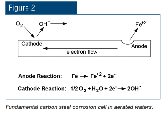
Iron is oxidized at the anode and enters solution as the ferrous ion (Fe+2). The process releases electrons that flow through the metal to the cathode, where the electrons reduce dissolved oxygen to hydroxyl ions (OH–). Hydroxyl ions then react with the solvated iron ions to complete the electrical circuit and form an initial product of Fe(OH)2, which continues to oxidize to eventually form rust, with a basic formula of Fe2O3∙xH2O. Uncontrolled oxygen attack can cause severe damage in piping networks and also generate deposits that may partially or completely restrict flow.
Other cathodic reactions are possible. One of the most common is corrosion in acidic solutions, where the cathodic reaction is:
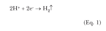
This corrosion mechanism can be easily demonstrated in the lab by placing an iron bar in a solution of hydrochloric acid. Almost immediately, hydrogen bubbles begin to appear while the metal rapidly disintegrates.
Corrosion inhibitors function by slowing down reactions at either the anode, the cathode or sometimes both. This now leads to discussion of a very popular program from the last century that was simplistic in nature but provided both good scale and corrosion control. Environmental issues required abandonment of the technique, which led to a major change in treatment method followed by the evolution occurring now.
The Good Old Days
In the years leading up to the 1970s, the most common method to protect carbon steel was based on chromate chemistry for corrosion protection, with sulfuric acid feed for scale control. The program inhibited calcium carbonate (CaCO3) scaling by the reaction of sulfuric acid with bicarbonate ions (HCO3–) to convert the ions to CO2, which escape as gas and lower the scaling tendency of the solution. Eq. 2 is representative of this chemistry:
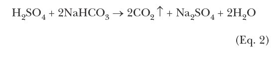
A typical pH control range was at or near 6.5 to 7.0. The second compound in the formulation, disodium chromate (Na2Cr2O7), provides chromate ions
that react with carbon steel to establish a protective, pseudo-stainless steel layer, particularly in the oxygensaturated cooling water generated by cooling towers. Acid-chromate programs performed extremely well in many applications, and chemistry control was quite straightforward.
For heat exchangers with copper alloy tubes, supplemental azole chemistry was, and still is, common to protect these metals. This paper does not explore azole chemistry in depth, but in brief azoles are organic compounds (a benzene ring at the core) with nitrogen functional groups.
The nitrogen groups attach to copper, with the plate-like organic rings forming a monomolecular layer on the metal surface to protect it from the environment. A variety of azoles, with various side groups, have been developed to improve bonding properties and also to increase azole resistance to degradation by other chemicals such as oxidizing biocides.
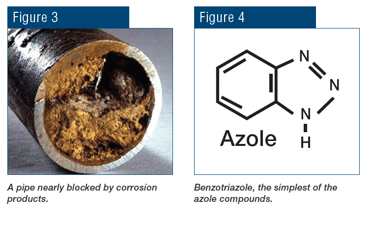
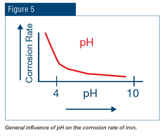
Bye-Bye Chromate
Increased understanding of the toxicity of hexavalent chromium, in large part due to the efforts of Erin Brockovich, led to a ban on chromium discharge to the environment, which essentially eliminated chromate treatment for open cooling water systems. The replacement program was radically different, with a key concept being operation at an alkaline pH to assist with corrosion control.
The Emergence of Phosphate/Phosphonate Chemistry
Treatment quickly evolved to phosphate-based chemistry for both scale and corrosion prevention. The programs typically function at a mildly alkaline pH, which minimizes general corrosion.
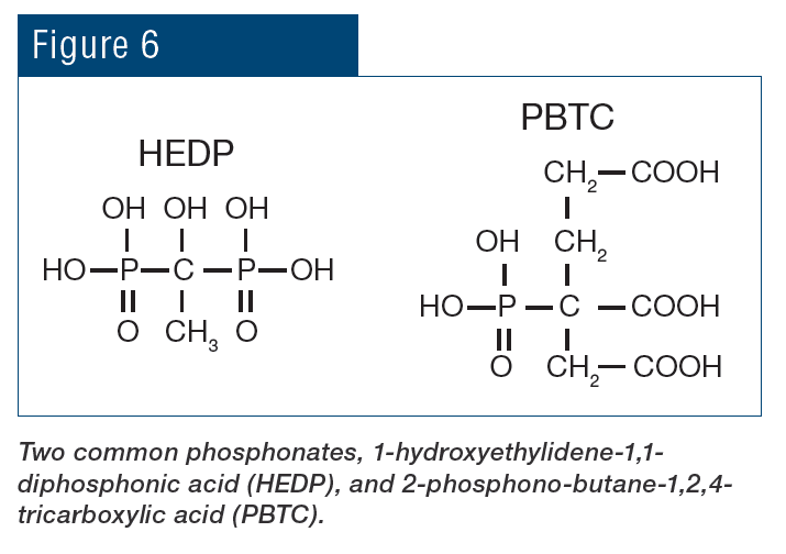
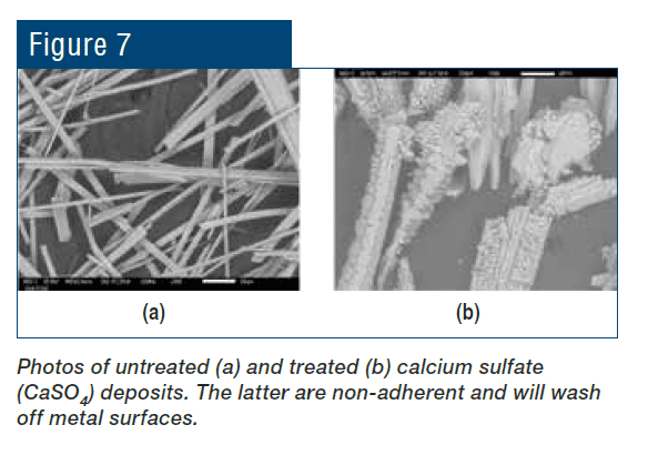
Beyond the pH aspect, the chemistry also provides additional corrosion protection because phosphate will react with ferrous ions (Fe+2) produced at anodic sites to form a reaction-limiting deposit, while calcium phosphate [Ca3(PO4)2] precipitates in the local alkaline environment at cathodic sites to inhibit electron transfer. However, even small upsets in phosphate programs can cause severe calcium phosphate fouling, and, at one time, excess Ca3(PO4)2 deposition became almost as great a problem as calcium carbonate scaling had been before. Accordingly, treatment methods evolved to more forgiving methodologies, where in many cases the backbone of these programs is organic phosphates (phosphonates).
Phosphonates attach to deposits as they are forming and disrupt crystal growth and lattice strength.
A common phosphate/phosphonate treatment program might include one or perhaps two of the phosphonate compounds in low mg/L dosages for primary scale control, 5–15 mg/L or so of orthophosphate for additional scale control and corrosion protection, and perhaps 0.5–2.5 mg/L of zinc. Zinc reacts with the hydroxyl ions generated at cathodes to form a precipitate [Zn(OH)2], which provides additional cathodic protection. (It should be noted that zinc discharge is also coming under tighter regulations.) Typically included in these formulations is 5–10 mg/L of organic polymer for control of calcium phosphate deposition.
Phosphate/phosphonate programs are far from simple, and under- or overfeed can result in either corrosion or scale formation. Even with seemingly proper chemistry, the corrosion-inhibiting deposits are porous, and also may wash away. And, with respect to environmental concerns, phosphorus discharge presents increasingly difficult problems.
Phosphorus, along with nitrogen and carbon, is a macronutrient that is essential for all life forms. Algae derive their carbon requirements from inorganic bicarbonate and carbonate, utilizing energy from sunlight to convert the inorganic carbon into organic carbon for cellular tissue growth. Some species of algae are also capable of “fixing” atmospheric nitrogen
gas, using the nitrogenase enzyme to convert N2 into ammonia and other compounds required for the biosynthesis of nucleic acids and proteins. Common among the photosynthetic nitrogen-fixing species are cyanobacteria, commonly referred to as “blue-green algae.” Phosphorus is often the limiting nutrient for growth in aquatic systems because it is present in very low concentrations relative to that required by plants and microorganisms.
Cyanobacteria are known for their extensive and highly visible green blooms. Fig. 8 shows an aerial photograph of a cyanobacteria bloom in the shallow western basin of Lake Erie in 2011.
The unpleasant and unsightly algae growth in Lake Erie resulted in fouled beaches, sharply reduced tourism and a decline in fish populations. Apart from their noxious sensory impact, cyanobacteria also produce microcystins and other cyanotoxins that are toxic to fish, birds and mammals. Many readers are undoubtedly aware of massive toxic algae blooms in other locations, most notably Florida.
Phosphate/phosphonate chemistry also provides an essential nutrient, phosphorus, for microbiological growth in cooling towers, particularly algae.
Adequate control of algae may require a substantial feed of microbiocides, which can greatly increase the cost to treat the cooling water.
These issues are leading to a new evolution: cooling water treatment with polymers and no phosphorus (and often no zinc) component. Successful applications for scale control have long been known, but now new materials for corrosion inhibition are proving successful, including at steel plants.
The Emergence of Polymer Chemistry
Polymer formulations containing the carboxylate group have been successfully utilized for decades to control calcium carbonate (CaCO3) scale in cooling water.
However, many other deposits are possible, including calcium and magnesium silicates, calcium sulfate, calcium fluoride and manganese dioxide, to name some of the most common. The need to combat these
and other scale-formers has generated development of co- and ter-polymers, containing alternative or supplemental functional groups including sulfonates (SO3–), acrylamide (H2N-C-O) and others. The polymers inhibit scale formation by two mechanisms: ion sequestration and crystal modification.
But another very important question remains: “How effective is a non-P program for corrosion inhibition?” In the first place, non-P treatments have been designed to operate at an alkaline pH range (7–9), which tends to minimize general corrosion of metals. But even so, corrosion cells can still develop in an alkaline environment. The key is that the corrosion inhibitor establishes a direct protective barrier on metal surfaces. One product that has emerged, FlexPro®, combines a group of chemistries that “interact directly with metal surfaces to form a reactive polyhydroxy starch inhibitor (RPSI) complex that is independent of calcium, pH or other water chemistry constituents.”1
Full-scale application of the chemistry has proven very effective. In one instance at a large industrial complex in the southeastern U.S., RPSI replaced previous polyphosphate and then zinc chemistry. Carbon steel corrosion rates have been reduced from 0.20 to 0.25 mm/year to 0.0025 to 0.0075 mm/year. On a secondary note, the change from zinc to RPSI was in part influenced by problems with severe algae formation in a clarifier and recycle pond at the plant. The removal of phosphate from the water solved that difficulty.
In another example at a large chemical plant on the Gulf Coast, traditional phosphate chemistry proved satisfactory for corrosion control, but calcium phosphate deposits caused fouling in some of the plant’s plate-and-frame heat exchangers. Such exchangers are notorious for low-flow locations and deposit accumulation. Conversion to RPSI chemistry maintained excellent corrosion protection and eliminated phosphate deposition.
The water treatment chemistries and technologies discussed here are suitable for many industrial applications, as outlined in the following example from an SSAB rolling mill.
SSAB Experience
At the SSAB mill in Mobile, Ala., USA, the FlexPro chemistry has been applied to both the non-contact cooling system and to the hot strip mill direct-contact spray cooling system. Fig. 12 illustrates the reduction in corrosion rate following the change from phosphate chemistry to RPSI chemistry.
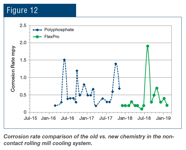
As can be seen, not only was the corrosion rate reduced, but control became more stable following introduction of the polymer chemistry. Even more pronounced results were achieved in the service water cooling system (Fig. 13).
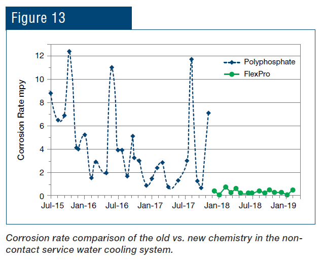
An application that is unique to steel mills as opposed to many other industries is the protection of metals cooled by direct sprays. The RPSI treatment has been implemented at the plant’s hot strip mill for more than a year, with results shown in Fig. 14.
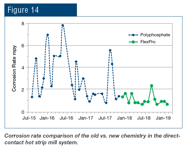
To re-emphasize, the key is that this chemistry establishes a direct protective layer on steel rather than relying on precipitation of phosphate compounds to inhibit corrosion. The change in chemistry has provided the following benefits to the plant:
- Elimination of 171,000 lbs. of phosphate dosing per year. None is now used or discharged.
- Elimination of zinc.
- Substantial reduction in corrosion across three plant cooling systems.
- Expected to increase work roll life based on superior corrosion performance.
- Same cost as the phosphate program.
Conclusion
Improvements in cooling water treatment stand to benefit many industries, not the least of which is the steel industry. Plant owners, operators and technical personnel now have access to new, enhanced tools to reduce corrosion and scaling in not only non-contact cooling water systems, but direct spray applications as well. Improvements can save plants significant costs via infrastructure protection and increased equipment reliability. And research and testing continue with regard to other potential process enhancements.
Disclaimer
Results are examples only. They are not guaranteed. Actual results may vary.
Reference
1 R.M. Post and R.P. Kalakodimi, “The Development and Application of Non-Phosphorus Corrosion Inhibitors for Cooling Water Systems,” World Energy Congress, Atlanta, Ga., USA, October 2017.
© 2020 by AIST. Distributed with permission of AIST. All other distribution is strictly prohibited.
The post Advances in Cooling Water Treatment for the Steel Industry appeared first on ChemTreat, Inc..
]]>The post Advanced Methods to Protect Cooling Water Systems appeared first on ChemTreat, Inc..
]]>By Brad Buecker & Ray Post
A concept often not well recognized is that cooling water chemistry programs are designed in large measure to treat metal surfaces and not just the cooling water itself. For many years over the last century, a common cooling tower treatment program utilized sulfuric acid to minimize scale formation, with chromate chemistry to inhibit corrosion of various metals in the system, most notably carbon steel. Almost universally, this method was discarded in the 1980s due to dawning knowledge of the toxicity of hexavalent chromium (Cr6+).
We encourage you to read the rest of the article online.
The post Advanced Methods to Protect Cooling Water Systems appeared first on ChemTreat, Inc..
]]>The post Environmentally Sustainable Water Treatment Methods Help Improve Cooling Tower Efficiency and Reliability appeared first on ChemTreat, Inc..
]]>Click here to read an article published by Chiller & Cooling Best Practices about key factors controlling cooling water chemistry and the advantages of phosphorus- and zinc-free cooling water treatment technology.
The post Environmentally Sustainable Water Treatment Methods Help Improve Cooling Tower Efficiency and Reliability appeared first on ChemTreat, Inc..
]]>The post Performance Improvement for Steam Generators appeared first on ChemTreat, Inc..
]]>Water/steam chemistry advancements at UIC
By Brad Buecker, Nigel Mohammed and Frank Murphy
The West Co-Gen Plant at the University of Illinois at Chicago (UIC) produces heating steam for the west side of the college campus, including approximately 50 buildings and the university hospitals (UIC and Rush). It also generates chilled water for the west campus and the UIC hospital. The original mindset was “water is water,” with minimal treatment utilized for normal operation. However, as numerous plant owners and operators have discovered, often to great regret, if plant makeup and process waters are not treated properly to remove impurities and optimize chemistry, severe corrosion, scaling, and fouling are the result.
Click here to read the rest of the article.
The post Performance Improvement for Steam Generators appeared first on ChemTreat, Inc..
]]>The post Plants Benefit From Better Cooling Tower Treatment by Brad Buecker & Ray Post appeared first on ChemTreat, Inc..
]]>Our earlier article “Improve Your Cooling Tower Treatment,” stressed the critical role that chemical treatment of cooling water systems plays for minimizing microbiological fouling, scaling and corrosion, and discussed a polymer chemistry that is replacing phosphate/phosphonate treatment. In this article, we look at two real-world examples of the benefits of that chemistry and point out the importance of not viewing corrosion inhibition in isolation.
Click here to read more.
The post Plants Benefit From Better Cooling Tower Treatment by Brad Buecker & Ray Post appeared first on ChemTreat, Inc..
]]>The post Improve Your Cooling Tower Treatment, by Brad Buecker & Ray Post appeared first on ChemTreat, Inc..
]]>Cooling water plays an essential role in process operations at many plants. For a majority of these facilities, the cooling system contains one or more cooling towers. The metals used in the tower, cooling water piping and heat exchangers may include carbon steel, galvanized steel, copper alloys and stainless steel. Protecting all these metals from corrosion and minimizing scaling and microbiological fouling in cooling systems pose ongoing challenges. Adding to the difficulty, operators face emerging restrictions on the discharge of a number of impurities in cooling tower blowdown, including phosphorus, zinc and other metals, biocide residuals, and dissolved and suspended solids. This article examines evolving chemistry that provides improved corrosion and fouling protection while also being more environmentally friendly than previous treatment methods.
Read the rest of this article by Brad Buecker and Ray Post online.
The post Improve Your Cooling Tower Treatment, by Brad Buecker & Ray Post appeared first on ChemTreat, Inc..
]]>